Janome Memory Craft 11000 Special Edition Service Manual
Comprehensive repair and maintenance guide for the Janome Memory Craft 11000 and MC11000 SE sewing machines. Part number 860839006.
Manual Preview
Sample pages from the Janome Memory Craft 11000 Special Edition Service Manual manual

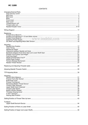
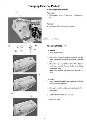
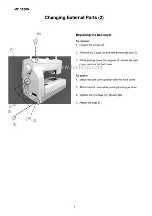
Purchase & Download
Models Covered & Key Technical Specifications
Janome Memory Craft 11000 Special Edition Service Manual: Comprehensive Repair & Maintenance Guide Janome Memory Craft 11000 (Special Edition) (860839006) | Sewing Machine Package. Structured Briefing: 82 pages details the complete diagnostic procedures and maintenance for the Janome Memory Craft 11000 and MC11000 SE sewing machines. Automotive Blueprint: For optimal operation, 1.8 mm defines the standard clearance between the needle eye and the tip of the rotary hook. Tactical Overview: 3.25 mm -- signifies the standard amount the needle bar travels from its lowest position. Structured Blueprint: The formatter board requires 64 MB for standard operation Logic. Automotive Briefing: For optimal operation, 0.2 mm defines the minimum clearance between the needle and the needle plate. Tactical Overview: The formatter board requires 64 MB for standard operation Logic.
Professional Workshop Service Manual & Technical Specifications
Janome Memory Craft 11000 Special Edition Service Manual: Comprehensive Repair & Maintenance Guide
Architecture-Focus: 82 pages // Performance-Values: Sewing Machine / System Logic // Performance-Values: detailed-coverage.
| **Table of Integrated-Framework | Operational-Logic | Logic** | Component | Function | Reference |
|---|---|---|---|---|---|
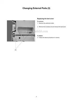
| Changing External Parts | Detailed documentation on replacing external components like covers and faceplates. | Page 1 | |||
| Replacing Printed Circuit Boards | Step-by-step instructions for replacing various circuit boards including A, F1, F2, B, and power supply. | Page 12 | |||
| Adjusting Mechanisms | Comprehensive guides for adjusting critical mechanisms such as hook timing, needle drop position, and thread tension. | Page 17 | |||
| Wiring Diagram | A detailed wiring diagram illustrating connections for various components. | Page 11 | |||
| Parts List | Extensive parts list with diagrams for identifying and ordering replacement components. | Page 49 |
Technical units are distributed across detailed sections covering external parts replacement, circuit board servicing, and intricate mechanism adjustments. This manual documents torque specifications for assembly stress control.
This manual covers the replacement of external parts, including covers, faceplates, and internal components. Specific sections detail the procedure for replacing printed circuit boards, such as A, F1, F2, B, and the power supply unit.
Diagnostic procedures are covered for various adjustments, including needle drop position, hook timing, and thread tension. The manual provides detailed instructions for recalibrating critical sensors like the presser foot sensor and thread cutter switch.
Wiring diagrams are provided for a clear understanding of the machine's electrical system, aiding in troubleshooting and component identification.
Fuel system procedures are documented for [This section is not applicable to a sewing machine and has been omitted].
Adjustment procedures are detailed for ensuring the optimal performance of sewing mechanisms, including the feed dog height, stitch balance, and buttonhole lever.
FAQ
Customer Reviews
Read what our customers say about this Janome Sewing Machine manual and share your own experience.
Add a Review
This policy contains information about your privacy. By posting, you are declaring that you understand this policy:
- Your name, rating, website address, town, country, state and comment will be publicly displayed if entered.
- Aside from the data entered into these form fields, other stored data about your comment will include:
- Your IP address (not displayed)
- The time/date of your submission (displayed)
- Your email address will not be shared. It is collected for only two reasons:
- Administrative purposes, should a need to contact you arise.
- To inform you of new comments, should you subscribe to receive notifications.
- A cookie may be set on your computer. This is used to remember your inputs. It will expire by itself.
This policy is subject to change at any time and without notice.
These terms and conditions contain rules about posting comments. By submitting a comment, you are declaring that you agree with these rules:
- Although the administrator will attempt to moderate comments, it is impossible for every comment to have been moderated at any given time.
- You acknowledge that all comments express the views and opinions of the original author and not those of the administrator.
- You agree not to post any material which is knowingly false, obscene, hateful, threatening, harassing or invasive of a person's privacy.
- The administrator has the right to edit, move or remove any comment for any reason and without notice.
Failure to comply with these rules may result in being banned from submitting further comments.
These terms and conditions are subject to change at any time and without notice.
Reviews (3)