2013 Nissan GT-R R35 Audio, Visual & Navigation System manual
Product Gallery
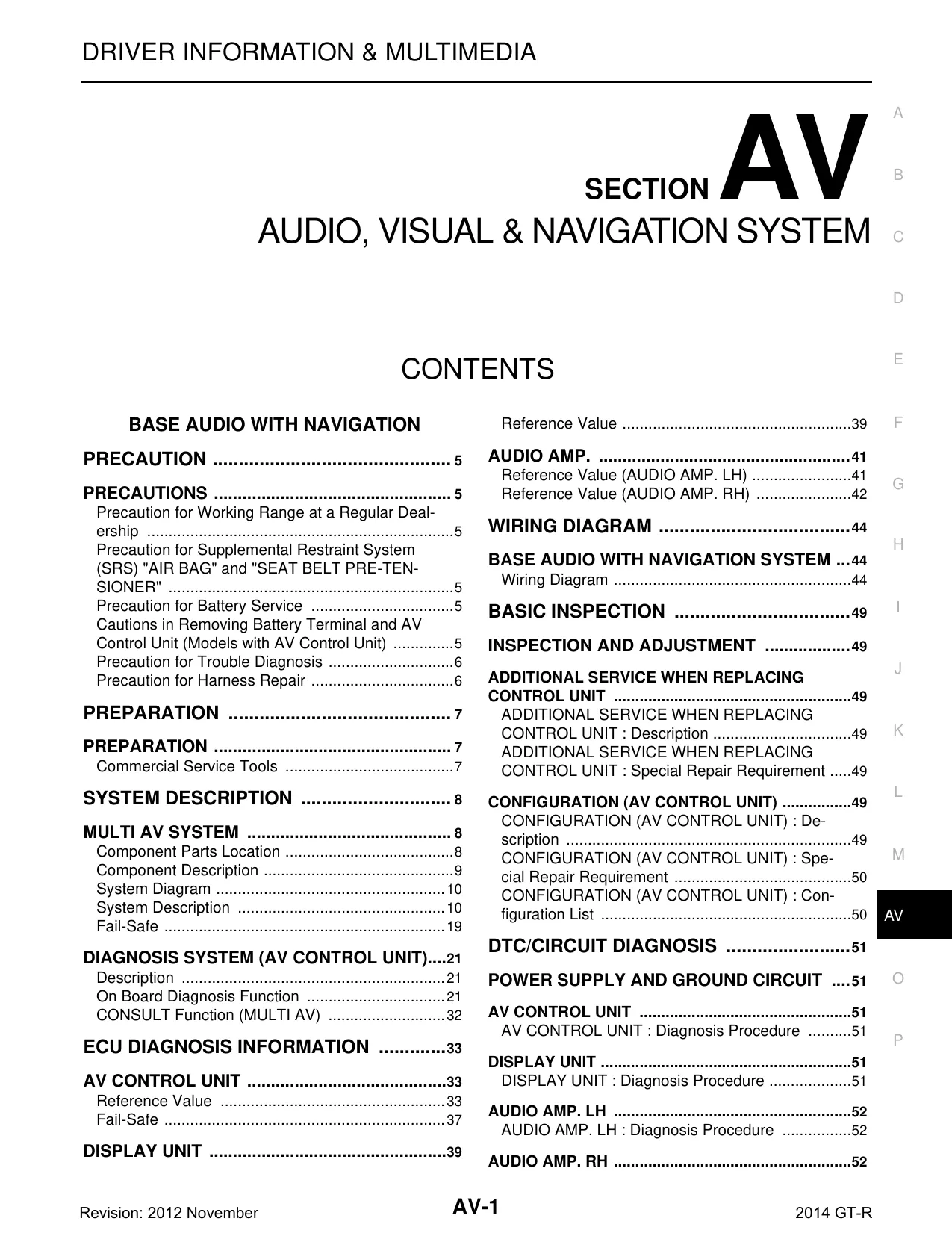
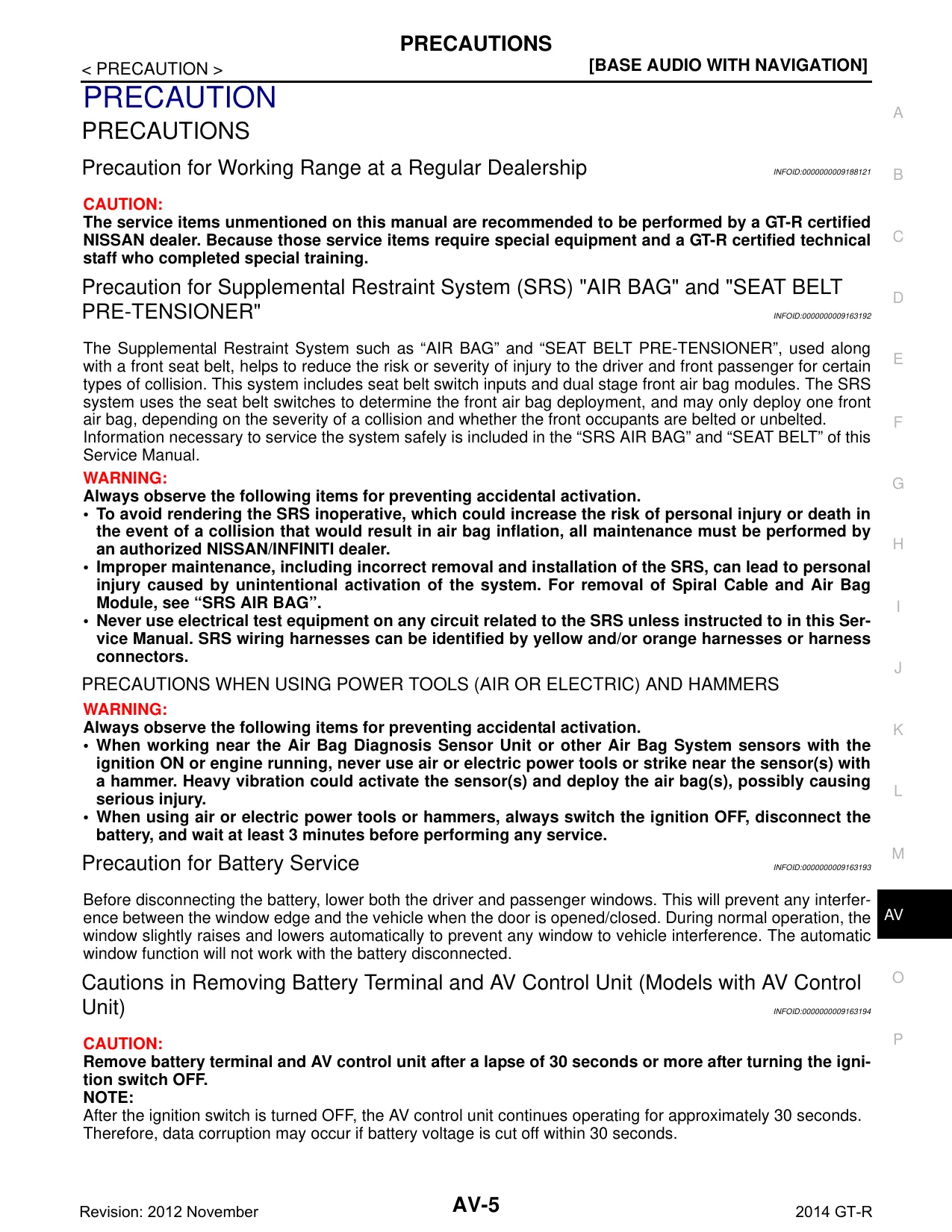
Sample pages from the 2013 Nissan GT-R R35 Audio, Visual & Navigation System manual manual

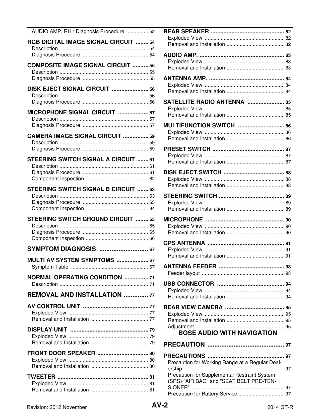
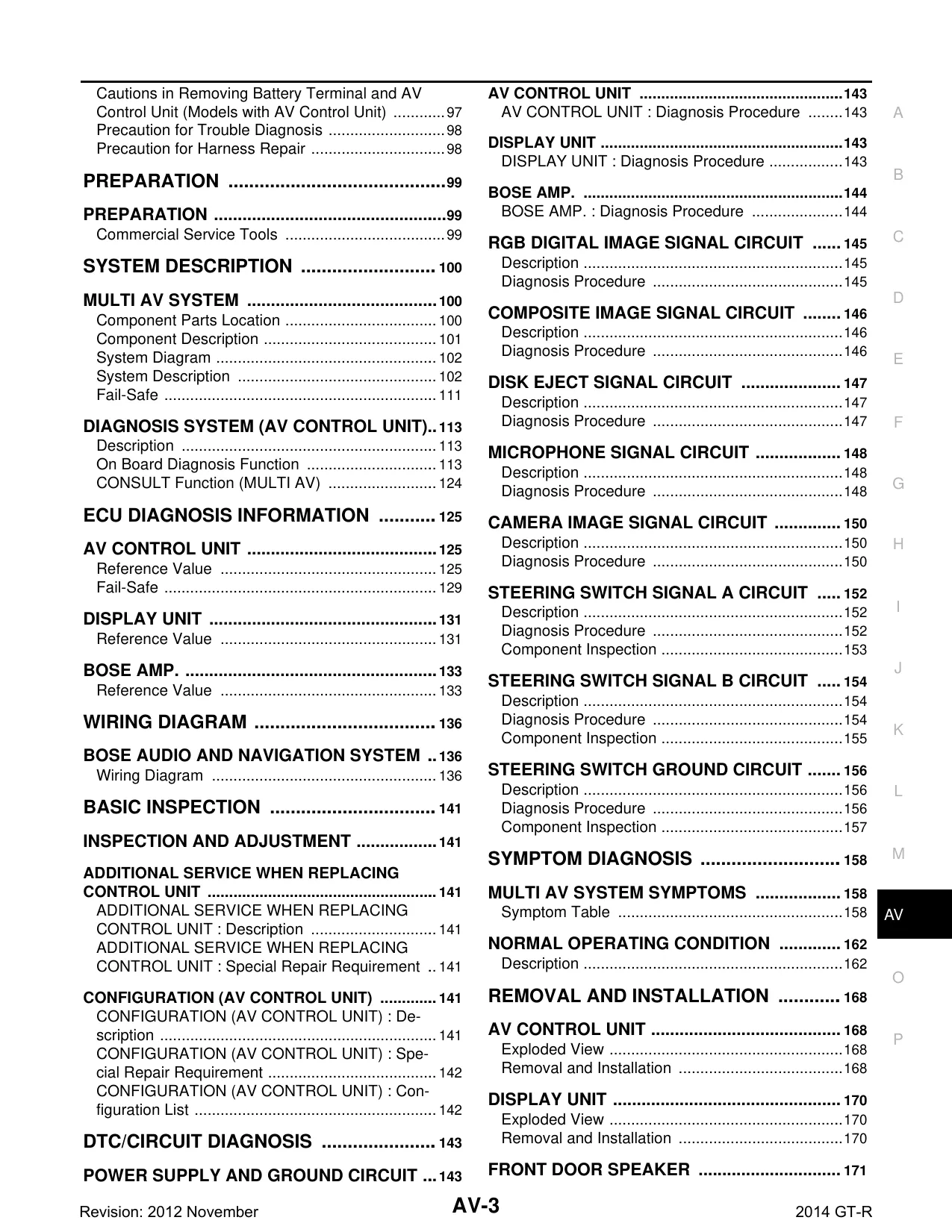
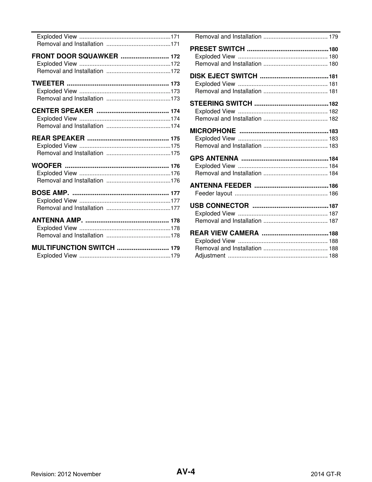
Purchase Information
2013 Nissan GT-R R35 Audio, Visual & Navigation System manual - Technical Specifications
- File Size:
- 33.32 MB
- File Type:
- ZIP
- Language:
- English
- Printable:
- Yes
- Estimated Download Time:
- 0.68 Minutes
- Delivery Format:
- Digital (PDF) - Instant Access
- Category:
- Car
- Brand:
- Nissan
Nissan Models and Parts Covered in this Car Manual
GT-R R35 / Nissan
- Nissan GT-R R35 Premium
- Nissan GT-R R35 Black Edition
Production year(s): 2013
Nissan 2013 Nissan GT-R R35 Audio, Visual & Navigation System manual - Complete Manual Information
Table of Contents
Base Audio with Navigation
- Precaution
- Precaution for Working Range at a Regular Dealership
- Precaution for Supplemental Restraint System (SRS) "AIR BAG" and "SEAT BELT PRE-TENSIONER"
- Precaution for Battery Service
- Cautions in Removing Battery Terminal and AV Control Unit (Models with AV Control Unit)
- Precaution for Trouble Diagnosis
- Precaution for Harness Repair
- Preparation
- Commercial Service Tools
System Description
- Multi AV System
- Component Parts Location
- Component Description
- System Diagram
- System Description
- Fail-Safe
- Diagnosis System (AV Control Unit)
- Description
- On Board Diagnosis Function
- CONSULT Function (MULTI AV)
ECU Diagnosis Information
- AV Control Unit
- Reference Value
- Fail-Safe
- Display Unit
- Reference Value
Audio AMP.
- Audio AMP. (LH)
- Reference Value
- Audio AMP. (RH)
- Reference Value
Wiring Diagram
- Base Audio with Navigation System
- Wiring Diagram
Basic Inspection
- Inspection and Adjustment
- Additional Service when Replacing Control Unit
- Description
- Special Repair Requirement
- Additional Service when Replacing Control Unit
- Configuration (AV Control Unit)
- Description
- Special Repair Requirement
- Configuration List
DTC/Circuit Diagnosis
- Power Supply and Ground Circuit
- AV Control Unit
- Diagnosis Procedure
- Display Unit
- Diagnosis Procedure
- Audio AMP. (BOSE AMP.)
- Diagnosis Procedure
- RGB Digital Image Signal Circuit
- Description
- Diagnosis Procedure
- Composite Image Signal Circuit
- Description
- Diagnosis Procedure
- Disk Eject Signal Circuit
- Description
- Diagnosis Procedure
- Microphone Signal Circuit
- Description
- Diagnosis Procedure
- Camera Image Signal Circuit
- Description
- Diagnosis Procedure
- Steering Switch Signal A Circuit
- Description
- Diagnosis Procedure
- Component Inspection
- Steering Switch Signal B Circuit
- Description
- Diagnosis Procedure
- Component Inspection
- Steering Switch Ground Circuit
- Description
- Diagnosis Procedure
- Component Inspection
- AV Control Unit
Symptom Diagnosis
- Multi AV System Symptoms
- Symptom Table
- Normal Operating Condition
- Description
Removal and Installation
- AV Control Unit
- Exploded View
- Removal and Installation
- Display Unit
- Exploded View
- Removal and Installation
- Front Door Speaker
- Exploded View
- Removal and Installation
- Tweeter
- Exploded View
- Removal and Installation
- Rear Speaker
- Exploded View
- Removal and Installation
- Audio AMP. (BOSE AMP.)
- Exploded View
- Removal and Installation
- Antenna AMP.
- Exploded View
- Removal and Installation
- Satellite Radio Antenna
- Exploded View
- Removal and Installation
- Multifunction Switch
- Exploded View
- Removal and Installation
- Preset Switch
- Exploded View
- Removal and Installation
- Disk Eject Switch
- Exploded View
- Removal and Installation
- Steering Switch
- Exploded View
- Removal and Installation
- Microphone
- Exploded View
- Removal and Installation
- GPS Antenna
- Exploded View
- Removal and Installation
- Antenna Feeder
- Feeder layout
- USB Connector
- Exploded View
- Removal and Installation
- Rear View Camera
- Exploded View
- Removal and Installation
- Adjustment
BOSE Audio with Navigation
- Precaution
- Precaution for Working Range at a Regular Dealership
- Precaution for Supplemental Restraint System (SRS) "AIR BAG" and "SEAT BELT PRE-TENSIONER"
- Precaution for Battery Service
- Cautions in Removing Battery Terminal and AV Control Unit (Models with AV Control Unit)
- Precaution for Trouble Diagnosis
- Precaution for Harness Repair
- Preparation
- Commercial Service Tools
System Description
- Multi AV System
- Component Parts Location
- Component Description
- System Diagram
- System Description
- Fail-Safe
- Diagnosis System (AV Control Unit)
- Description
- On Board Diagnosis Function
- CONSULT Function (MULTI AV)
ECU Diagnosis Information
- AV Control Unit
- Reference Value
- Fail-Safe
- Display Unit
- Reference Value
- BOSE AMP.
- Reference Value
Wiring Diagram
- BOSE Audio and Navigation System
- Wiring Diagram
Basic Inspection
- Inspection and Adjustment
- Additional Service when Replacing Control Unit
- Description
- Special Repair Requirement
- Additional Service when Replacing Control Unit
- Configuration (AV Control Unit)
- Description
- Special Repair Requirement
- Configuration List
DTC/Circuit Diagnosis
- Power Supply and Ground Circuit
- AV Control Unit
- Diagnosis Procedure
- Display Unit
- Diagnosis Procedure
- BOSE AMP.
- Diagnosis Procedure
- RGB Digital Image Signal Circuit
- Description
- Diagnosis Procedure
- Composite Image Signal Circuit
- Description
- Diagnosis Procedure
- Disk Eject Signal Circuit
- Description
- Diagnosis Procedure
- Microphone Signal Circuit
- Description
- Diagnosis Procedure
- Camera Image Signal Circuit
- Description
- Diagnosis Procedure
- Steering Switch Signal A Circuit
- Description
- Diagnosis Procedure
- Component Inspection
- Steering Switch Signal B Circuit
- Description
- Diagnosis Procedure
- Component Inspection
- Steering Switch Ground Circuit
- Description
- Diagnosis Procedure
- Component Inspection
- AV Control Unit
Symptom Diagnosis
- Multi AV System Symptoms
- Symptom Table
- Normal Operating Condition
- Description
Removal and Installation
- AV Control Unit
- Exploded View
- Removal and Installation
- Display Unit
- Exploded View
- Removal and Installation
- Front Door Speaker
- Exploded View
- Removal and Installation
- Tweeter
- Exploded View
- Removal and Installation
- Rear Speaker
- Exploded View
- Removal and Installation
- Audio AMP. (BOSE AMP.)
- Exploded View
- Removal and Installation
- Antenna AMP.
- Exploded View
- Removal and Installation
- Satellite Radio Antenna
- Exploded View
- Removal and Installation
- Multifunction Switch
- Exploded View
- Removal and Installation
- Preset Switch
- Exploded View
- Removal and Installation
- Disk Eject Switch
- Exploded View
- Removal and Installation
- Steering Switch
- Exploded View
- Removal and Installation
- Microphone
- Exploded View
- Removal and Installation
- GPS Antenna
- Exploded View
- Removal and Installation
- Antenna Feeder
- Feeder layout
- USB Connector
- Exploded View
- Removal and Installation
- Rear View Camera
- Exploded View
- Removal and Installation
- Adjustment
Download Instructions for Nissan Car Manual
Frequently Asked Questions - Nissan Car Manual
What does this Nissan manual cover?
This comprehensive service manual covers detailed repair procedures, maintenance schedules, troubleshooting guides, and technical specifications for 2013 Nissan GT-R R35 Audio, Visual & Navigation System manual. It includes information for the following models: **GT-R R35 / Nissan** - Nissan GT-R R35 Premium - Nissan GT-R R35 Black Edition Production year(s): 2013 .
Is this manual suitable for beginners?
Yes, this Nissan manual is designed for both professional technicians and DIY enthusiasts. It includes step-by-step procedures with clear illustrations and safety guidelines for Car maintenance and repair.
What file format will I receive?
You will receive this manual as a ZIP file (33.32 MB), which is compatible with all devices. The manual is fully searchable and printable for your convenience.
How quickly can I access the manual after purchase?
You'll receive instant access to your Nissan Car manual immediately after payment completion. The download link is valid for 3 days, with lifetime re-download guarantee.
Does this manual include wiring diagrams?
Yes, this automotive service manual typically includes electrical wiring diagrams, component locations, and diagnostic procedures specific to your Nissan vehicle model.
Can I print specific sections of the manual?
Absolutely! This digital manual allows you to print any section you need, from individual pages to complete chapters, making it perfect for workshop use.
Nissan 2013 Nissan GT-R R35 Audio, Visual & Navigation System manual Customer Reviews and Feedback
Read what our customers say about this Nissan Car manual and share your own experience.
Add Comment
This policy contains information about your privacy. By posting, you are declaring that you understand this policy:
- Your name, rating, website address, town, country, state and comment will be publicly displayed if entered.
- Aside from the data entered into these form fields, other stored data about your comment will include:
- Your IP address (not displayed)
- The time/date of your submission (displayed)
- Your email address will not be shared. It is collected for only two reasons:
- Administrative purposes, should a need to contact you arise.
- To inform you of new comments, should you subscribe to receive notifications.
- A cookie may be set on your computer. This is used to remember your inputs. It will expire by itself.
This policy is subject to change at any time and without notice.
These terms and conditions contain rules about posting comments. By submitting a comment, you are declaring that you agree with these rules:
- Although the administrator will attempt to moderate comments, it is impossible for every comment to have been moderated at any given time.
- You acknowledge that all comments express the views and opinions of the original author and not those of the administrator.
- You agree not to post any material which is knowingly false, obscene, hateful, threatening, harassing or invasive of a person's privacy.
- The administrator has the right to edit, move or remove any comment for any reason and without notice.
Failure to comply with these rules may result in being banned from submitting further comments.
These terms and conditions are subject to change at any time and without notice.
Comments (5)