John Deere 310E Backhoe Loader Factory Workshop Manual (P/N TM1649)
1,081 Pages • 162.11 MB • Instant, Printable PDF
John Deere Models Covered & Key Technical Specifications
Models: 310E
Model Years: 1997–2002 (1997, 1998, 1999, 2000, 2001, 2002)
Technical Data:
-
Engine: John Deere 4045 (4.5 L, 4-cylinder)
-
Power: 57 kW (76 hp) gross SAE @ 2200 rpm
-
Max Engine Net Torque: 296 N·m (218 lb-ft)
-
Electrical System: 12 volts, 65 amp alternator
-
Fuel Tank Capacity: 106 L (28 gal)
-
Hydraulic Reservoir Capacity: 37 L (39 qt)
-
Transmission: 4-speed helical gear with torque converter
-
Hydraulic Pressure Relief Setting (Backhoe): 25 000 kPa (3625 psi)
-
Hydraulic Pressure Relief Setting (Loader): 19 000 kPa (2750 psi)
John Deere Manual Features & Content Preview
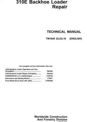
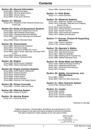
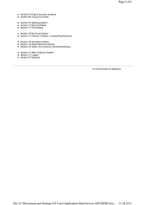
John Deere Technical Manual TM1649, 22JUL10 (English) is the factory repair publication for the 310E Backhoe Loader. The 1,081-page PDF is organized into 18 numbered sections and covers machine-level removal, disassembly, inspection, assembly, adjustment, and repair.
- Matches 310E configurations using the 4045D naturally aspirated or 4045T altitude-compensated engine installation, non-powered front axle or APL-2025 MFWD, standard or extendible dipperstick, ROPS or cab, and equipment such as ride control, auxiliary flow, and the multi-purpose loader bucket.
- Takes the transmission through removal, forward and reverse clutch-pack repair, synchronizer and output-shaft service, MFWD output-shaft work, control-valve and charge-pump repair, and complete case reassembly.
- Details rear-axle removal and overhaul, planetary and differential service, ring-and-pinion setup, park-brake repair, service-brake inspection, brake-valve repair, pedal adjustment, brake bleeding, steering-valve service, cylinder repair, toe-in, and MFWD tracking adjustment.
- Covers the main hydraulic pump, reservoir and coolers, loader and backhoe control valves, relief and anti-cavitation valves, ride-control accumulator charging, and repair of the 120- and 125-series hydraulic cylinders.
- Documents loader removal, bucket and cutting-edge repair, multi-purpose bucket service, self-leveling and return-to-dig adjustment, plus backhoe boom, dipperstick, swing-frame, stabilizer, and extendible-dipperstick work.
- Handles engine removal, cooling-system service, air-intake leakage testing, cold-starting aid, exhaust and fuel-tank work, battery and harness repair, connector and fuse service, cab/ROPS, seat and window repair, hood/grille/fender service, and R134a A/C recovery, evacuation, charging, and leak testing.
- Supplies component-specific torque tables, fluid-capacity and ambient-temperature viscosity data, lift-capacity charts, wear limits, clearances, exploded assemblies, cross-sections, component-location views, and factory tool references.
Variant and serial-specific coverage
The rear-axle capacity data changes at S.N. 851674, and the backhoe stabilizer-valve linkage is split into separate procedures through S.N. 874257 and from S.N. 874258. The book also distinguishes earlier and later flow-control relief valves, non-powered and MFWD front-axle arrangements, standard and extendible dippersticks, cab and ROPS structures, and optional ride-control and auxiliary-hydraulic equipment.
Transmission coverage goes well past removal and installation. Separate procedures address the converter side of the case, forward and reverse clutch packs, input drive shaft, synchronizer, intermediate and rear output shafts, MFWD output shaft, idler shaft, hydraulic control valve, charge pump, and manifold-plate solenoids. The rear-axle chapters add pinion-depth calculations, shim selection, bearing rolling drag, backlash, gear-tooth contact checks, differential-lock work, and final service-brake checks.
The manual flags expensive mistakes: forward and reverse clutch packs must return to the same bores, hydraulic valve spools must stay with their original sections and installation orientation for proper function, and cylinder parts must remain aligned so cap seals are not cut or distorted. Ring gear and pinion are treated as a matched assembly, with the related setup checks documented before the axle is closed.
Tools, diagrams, and workshop references
Factory tool listings identify equipment by number, including the JDG1056 axle spanner nut wrench, JDG1057 MFWD shaft-seal installer, JDG393 engine lifting bracket, JDG140 METRIMATE extractor, JDG1290 relief-valve seal installer, and JDG734 spool-valve seal installation tool. The A/C section specifies R134a recovery, recycling, and charging equipment, while dealer-fabricated drawings cover transmission supports, rear-axle mounting and rolling-torque fixtures, the cab/ROPS lift bracket, and the compressor holding fixture.
Representative illustrations include the Rear Output Shaft Cross Section View, MFWD Shaft Cross Section View, Park Brake Cross Section, Cross Section of Steering Valve, Heater/Blower Assembly with Air Conditioning Assembly Diagram, and Backhoe Hydraulic-Component Location. Electrical repair is supported by harness and component-location views for the cab roof, consoles, engine, blower, A/C compressor, auxiliary-flow system, and ride-control system, plus Kostal, DEUTSCH, and WEATHER PACK connector service.
Important scope limits
TM1649 is the repair half of the factory service information. The separate TM1648 Operation and Test publication is referenced for machine diagnosis, transmission and brake pressure or leakage tests, and certain hydraulic relief-valve adjustments. Internal PowerTech 4.5 L engine work requires CTM104; complete Bosch alternator repair and starting-motor repair require CTM77; and internal APL-2025 MFWD axle repair requires CTM4509. The torque converter is covered as a removal-and-replacement assembly and is specifically identified as having no internal service parts.
Raised loader and backhoe structures, stored hydraulic or accumulator pressure, heavy driveline components, tires, batteries, welding, and refrigerant work all carry machine-specific safety procedures. Use the boom lock and proper supports, relieve pressure before opening a circuit, isolate electrical power where directed, and follow the complete OEM procedure with the specified tools and training.
Customer Reviews
Read what our customers say about this John Deere Backhoe Loader manual and share your own experience.