Manual for Nissan Pathfinder, 1997 PDF
Manual Preview
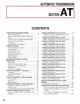
Sample pages from the Manual for Nissan Pathfinder, 1997 PDF manual

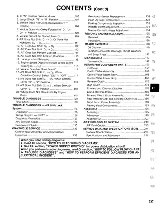
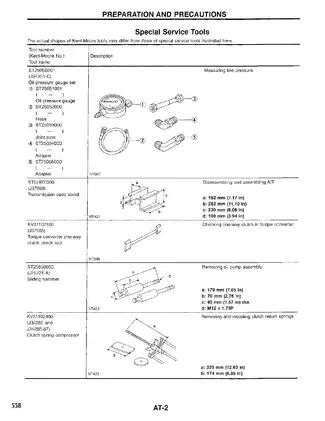
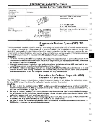
Purchase & Download
Models Covered & Key Technical Specifications
Pathfinder R50 series / Nissan Motor Corporation, Ltd
- Nissan Pathfinder XE
- Nissan Pathfinder LE
- Nissan Pathfinder SE
Production/model years: 1997
Professional Workshop Service Manual & Technical Specifications
Table of Contents:
PREPARATION AND PRECAUTIONS
- Special Service Tools
- Special Tools
- Supplemental Restraint System (SRS) "AIR BAG"
- Precautions for On-Board Diagnostic (OBD) System of A/T
- Service Notice and General Precautions
- How to Perform Efficient Diagnosis for an Electrical Incident
- Wiring Diagram — How to Read
DESCRIPTION
- Description
- Hydraulic Control System Diagram
- A/T Electrical Parts Location
- A/T Gear Shift Control
- System Description
ON-BOARD DIAGNOSTIC SYSTEM DESCRIPTION
- Diagnostic Trouble Code (DTC) Indication
- TCM Inspection Procedure
- How to Erase DTC
- Freeze Frame Data
- Overall Function Check
- DTC for OBD System
TROUBLE DIAGNOSIS
- Diagnostic Procedure — Basic Inspection
- Trouble Diagnosis — Basic Inspection
- Preliminary Check
- Diagnostic Trouble Code Chart
- Basic Inspection Procedure
- Harness Wire Layout
- Trouble Diagnosis for DTC P0716
- A/T Fluid Temperature Sensor Circuit and A/T Fluid Temperature Sensor
- Trouble Diagnosis for DTC P0720
- A/T Speed Sensor
- Trouble Diagnosis for DTC P0725
- Engine Speed Signal
- Trouble Diagnosis for DTC P0731
- First Gear Function
- Trouble Diagnosis for DTC P0732
- Second Gear Function
- Trouble Diagnosis for DTC P0733
- Third Gear Function
- Trouble Diagnosis for DTC P0734
- Fourth Gear Function
- Trouble Diagnosis for DTC P0735
- Fifth Gear Function
- Trouble Diagnosis for DTC P0744
- A/T TCC Function
- Trouble Diagnosis for DTC P0750
- Shift Solenoid Valve A
- Trouble Diagnosis for DTC P0755
- Shift Solenoid Valve B
- Trouble Diagnosis for DTC P0760
- Shift Solenoid Valve C
- Trouble Diagnosis for DTC P0765
- Shift Solenoid Valve D
- Trouble Diagnosis for DTC P0770
- Shift Solenoid Valve E
- Trouble Diagnosis for DTC P1705
- A/T Inductive Signal
- Trouble Diagnosis for DTC P1750
- A/T Torque Converter Clutch Solenoid Valve
- Trouble Diagnosis for DTC P1757
- A/T Hydraulic Pressure Control
- Trouble Diagnosis for DTC P1760
- A/T Overrun Clutch Solenoid Valve
- Trouble Diagnosis for DTC P1762
- A/T Overrun Clutch Solenoid Valve
TROUBLE DIAGNOSIS — A/T SHIFT LOCK
- System Description
- Wiring Diagram — Shift Lock
- Component Parts Location
- Mechanical Parts
- Electrical Parts
- Inspection and Adjustment
- Trouble Diagnosis Chart
- Diagnosis Procedure for DTC P0850
- Trouble Diagnosis for "P" Position Switch
- Trouble Diagnosis for "R" Position Switch
- Trouble Diagnosis for "N" Position Switch
- Trouble Diagnosis for "D" Position Switch
- Trouble Diagnosis for "2" Position Switch
- Trouble Diagnosis for "1" Position Switch
- Trouble Diagnosis for "L" Position Switch
REMOVAL AND INSTALLATION
- Removal and Installation
MAJOR OVERHAUL
- Major Overhaul
- Transmission Disassembly
- Transmission Assembly
REPAIR FOR COMPONENT PARTS
- Oil Pump
- Control Valve Assembly
- Control Valve Upper Body
- Control Valve Lower Body
- Torque Converter Clutch
- Front Brake Assembly
- Low & Reverse Brake Assembly
- Clutch Assembly
- Reverse Clutch Assembly
- Forward Clutch Assembly
- One-Way Clutch
- Forward and Reverse Clutch Hub
- Band Servo Piston Assembly
- Parking Pawl Components
ASSEMBLY
- Assembly
- Adjustment
A/T FLUID COOLER SYSTEM
- A/T Fluid Cooler
SERVICE DATA AND SPECIFICATIONS (SDS)
- Service Data and Specifications
- Specifications for Refill
FAQ
Customer Reviews
Read what our customers say about this Nissan SUV manual and share your own experience.
Add a Review
This policy contains information about your privacy. By posting, you are declaring that you understand this policy:
- Your name, rating, website address, town, country, state and comment will be publicly displayed if entered.
- Aside from the data entered into these form fields, other stored data about your comment will include:
- Your IP address (not displayed)
- The time/date of your submission (displayed)
- Your email address will not be shared. It is collected for only two reasons:
- Administrative purposes, should a need to contact you arise.
- To inform you of new comments, should you subscribe to receive notifications.
- A cookie may be set on your computer. This is used to remember your inputs. It will expire by itself.
This policy is subject to change at any time and without notice.
These terms and conditions contain rules about posting comments. By submitting a comment, you are declaring that you agree with these rules:
- Although the administrator will attempt to moderate comments, it is impossible for every comment to have been moderated at any given time.
- You acknowledge that all comments express the views and opinions of the original author and not those of the administrator.
- You agree not to post any material which is knowingly false, obscene, hateful, threatening, harassing or invasive of a person's privacy.
- The administrator has the right to edit, move or remove any comment for any reason and without notice.
Failure to comply with these rules may result in being banned from submitting further comments.
These terms and conditions are subject to change at any time and without notice.
Reviews (4)