Essential Nissan Pathfinder manual: R50, 2003, PDF
Product Gallery
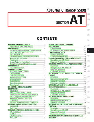
Sample pages from the Essential Nissan Pathfinder manual: R50, 2003, PDF manual

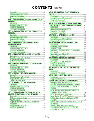
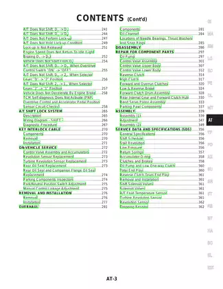
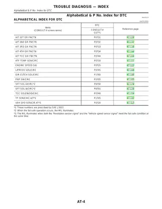
Purchase Information
2003 Nissan Pathfinder R50 series service manual - Technical Specifications
- File Size:
- 31.51 MB
- File Type:
- ZIP
- Language:
- English
- Pages:
- 1000
- Printable:
- Yes
- Estimated Download Time:
- 0.65 Minutes
- Delivery Format:
- Digital (PDF) - Instant Access
- Category:
- SUV
- Brand:
- Nissan
Nissan Models and Parts Covered in this SUV Manual
Pathfinder R50 series / Nissan Motor Corporation, Ltd
Production/model years: 2003
Complete Manual Information
Table of Contents
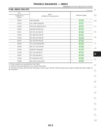
TROUBLE DIAGNOSIS - INDEX
- Alphabetical & P.No. Index for DTC
PRECAUTIONS
- Precautions for Supplemental Restraint System (SRS) "AIR BAG"
- Precautions for On Board Diagnostic (OBD) System of A/T
- Service Notice and General Precautions
PREPARATION
- Special Service Tools
- Commercial Service Tools
DESCRIPTION
- Description
- Electrical Unit Layout
- A/T Electrical Parts Location
- TCM and Engine Control System
- System Description
- System Diagram
- Control Signal Item
ON BOARD DIAGNOSTIC SYSTEM
- Diagnosis by CONSULT
- How to Erase DTC for OBD-II (Excluding Engine Control Module)
- Overall Function Check
- DTC Inspection Priority Chart
- DTC Index
TROUBLE DIAGNOSIS - INTRODUCTION
- Preliminary Check
- Basic Inspection Procedure
TROUBLE DIAGNOSIS - BASIC INSPECTION
- Trouble Diagnosis Chart by Symptom
- A/T Shift Schedule
- Line Pressure Test
TROUBLE DIAGNOSIS - GENERAL DESCRIPTION
- Symptom Chart
- TCM Terminal and Reference Value
TROUBLE DIAGNOSIS FOR POWER SUPPLY
- Diagnostic Procedure for A/T - MAIN POWER SUPPLY
- Diagnostic Procedure for A/T - IGNITION POWER SUPPLY
- Wiring Diagram - A/T - IPDM E/R
- Wiring Diagram - A/T - FUEL PUMP
TROUBLE DIAGNOSIS FOR DTC P0713
- ATF Fluid Temperature Sensor
TROUBLE DIAGNOSIS FOR DTC P0720
- Vehicle Speed Sensor (Revolution Sensor)
TROUBLE DIAGNOSIS FOR DTC P0731
- Incorrect Gear Ratio P0731
TROUBLE DIAGNOSIS FOR DTC P0732
- Incorrect Gear Ratio P0732
TROUBLE DIAGNOSIS FOR DTC P0733
- Incorrect Gear Ratio P0733
TROUBLE DIAGNOSIS FOR DTC P0734
- Incorrect Gear Ratio P0734
TROUBLE DIAGNOSIS FOR DTC P0735
- Incorrect Gear Ratio P0735
TROUBLE DIAGNOSIS FOR DTC P0744
- A/T TCC Function
TROUBLE DIAGNOSIS FOR DTC P0750
- Shift Solenoid Valve A
TROUBLE DIAGNOSIS FOR DTC P0755
- Shift Solenoid Valve B
TROUBLE DIAGNOSIS FOR DTC P0760
- Shift Solenoid Valve C
TROUBLE DIAGNOSIS FOR DTC P0765
- Shift Solenoid Valve D
TROUBLE DIAGNOSIS FOR DTC P0770
- Shift Solenoid Valve E
TROUBLE DIAGNOSIS FOR DTC P1705
- A/T Inductive Signal
TROUBLE DIAGNOSIS FOR DTC P1757
- A/T Hydraulic Pressure Control
TROUBLE DIAGNOSIS FOR DTC P1760
- A/T Overrun Clutch Solenoid Valve
TROUBLE DIAGNOSIS FOR DTC P1762
- A/T Overrun Clutch Solenoid Valve
TROUBLE DIAGNOSIS - A/T SHIFT LOCK SYSTEM
- Wiring Diagram
- Component Parts Location
- TCM Terminal and Reference Value
- Control Circuit Diagram
- Description
- Diagnostic Procedure
TROUBLE DIAGNOSIS - VEHICLE SPEED SENSOR MTR
- Wiring Diagram
- Component Parts Location
- TCM Terminal and Reference Value
- Control Circuit Diagram
- Description
- Diagnostic Procedure
TROUBLE DIAGNOSIS - INPUT SPEED SENSOR
- Wiring Diagram
- Component Parts Location
- TCM Terminal and Reference Value
- Control Circuit Diagram
- Description
- Diagnostic Procedure
TROUBLE DIAGNOSIS - OUTPUT SPEED SENSOR
- Wiring Diagram
- Component Parts Location
- TCM Terminal and Reference Value
- Control Circuit Diagram
- Description
- Diagnostic Procedure
REMOVAL AND INSTALLATION
- A/T Assembly
- Torque Converter
DISASSEMBLY AND ASSEMBLY
- Disassembly
- Assembly
A/T FLUID COOLER SYSTEM
- A/T Fluid Cooler
- Fluid Cooler System
SERVICE DATA AND SPECIFICATIONS (SDS)
- Service Data and Specifications
- Refill Capacities
- Recommended Fluids
- Maintenance and Lubrication
- The pricing of this manual is determined by the seller, not [RL] marketplace, so the same manual may be available at different prices on other pages. Be sure to compare prices before making your purchase.
Download Instructions for Nissan SUV Manual
Frequently Asked Questions - Nissan SUV Manual
What does this Nissan manual cover?
This comprehensive service manual covers detailed repair procedures, maintenance schedules, troubleshooting guides, and technical specifications for Essential Nissan Pathfinder manual: R50, 2003, PDF. It includes information for the following models: **Pathfinder R50 series / Nissan Motor Corporation, Ltd** Production/model years: 2003 .
Is this manual suitable for beginners?
Yes, this Nissan manual is designed for both professional technicians and DIY enthusiasts. It includes step-by-step procedures with clear illustrations and safety guidelines for SUV maintenance and repair.
What file format will I receive?
You will receive this manual as a ZIP file (31.51 MB), which is compatible with all devices. The manual is fully searchable and printable for your convenience.
How quickly can I access the manual after purchase?
You'll receive instant access to your Nissan SUV manual immediately after payment completion. The download link is valid for 3 days, with lifetime re-download guarantee.
Can I print specific sections of the manual?
Absolutely! This digital manual allows you to print any section you need, from individual pages to complete chapters, making it perfect for workshop use.
Customer Reviews and Feedback
Read what our customers say about this Nissan SUV manual and share your own experience.
Add Comment
This policy contains information about your privacy. By posting, you are declaring that you understand this policy:
- Your name, rating, website address, town, country, state and comment will be publicly displayed if entered.
- Aside from the data entered into these form fields, other stored data about your comment will include:
- Your IP address (not displayed)
- The time/date of your submission (displayed)
- Your email address will not be shared. It is collected for only two reasons:
- Administrative purposes, should a need to contact you arise.
- To inform you of new comments, should you subscribe to receive notifications.
- A cookie may be set on your computer. This is used to remember your inputs. It will expire by itself.
This policy is subject to change at any time and without notice.
These terms and conditions contain rules about posting comments. By submitting a comment, you are declaring that you agree with these rules:
- Although the administrator will attempt to moderate comments, it is impossible for every comment to have been moderated at any given time.
- You acknowledge that all comments express the views and opinions of the original author and not those of the administrator.
- You agree not to post any material which is knowingly false, obscene, hateful, threatening, harassing or invasive of a person's privacy.
- The administrator has the right to edit, move or remove any comment for any reason and without notice.
Failure to comply with these rules may result in being banned from submitting further comments.
These terms and conditions are subject to change at any time and without notice.
Comments (1)