2013–2014 Ducati Hypermotard SP Factory Service & Repair Manual (P/N 140403)
30 Pages • 63.40 MB • Printable PDFs (ZIP Download)
Ducati Models Covered & Key Technical Specifications
Models: Hypermotard SP, Hypermotard, Hyperstrada
Sub-models / Variants: 821 cc Testastretta 11-degree engine variants, SP model trim
Model Years: 2013–2014
-
Generator output: 500 W, 12 V
-
Starter motor power: 0.7 kW / 12 V
-
Battery charging system voltage: 14.5 V ± 0.5 at 3,000 rpm
-
Generator voltage output (2,000 rpm): 34 ± 5 V
-
Generator voltage output (6,000 rpm): 104 ± 10 V
-
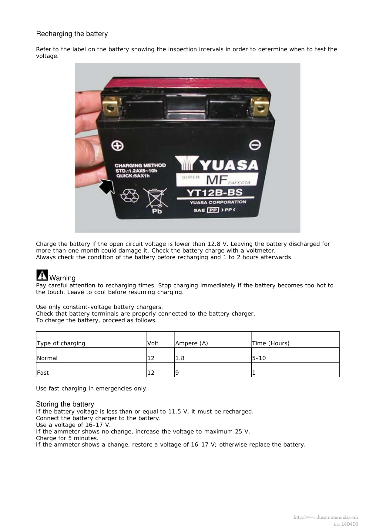
Standard battery charging (Normal): 1.8 A, 5–10 hours
-
Standard battery charging (Fast): 9 A, 1 hour
-
Battery terminal torque: 10 Nm ± 10%
-
Solenoid starter screw torque: 4 Nm ± 10%
-
Voltage test ambient temperature: 20 °C
Ducati Manual Features & Content Preview
- Covers 2013 Ducati Hypermotard SP engine, chassis, and electrical repair, with shared Hypermotard and Hyperstrada procedures and a separate 2013–2014 electrical supplement for all three models.
- Factory procedures cover engine removal, cylinder-head overhaul, desmodromic valve adjustment, timing-belt installation, and crankcase reassembly.
- Wet-clutch and six-speed gearbox sections detail disassembly, wear inspection, selector alignment, shaft shimming, and final engagement checks.
- ABS service includes DDS fault diagnosis, brake bleeding, control-unit replacement, and wheel-speed sensor air-gap adjustment.
- Chassis work covers steering-head bearings, fork and shock removal, swingarm service, and chain-and-sprocket replacement.
- Includes detailed wiring schematics, fuse identification charts, harness-routing views, and component-level torque tables for repair reference.
Model Coverage and File Contents
The workshop manual covers the Testastretta 11° 821 cc liquid-cooled L-twin and identifies the SP’s Marzocchi front fork and Öhlins rear shock. Variant-specific material distinguishes chain adjustment for the standard model, SP, Hyperstrada, and low-seat Hyperstrada, along with Hyperstrada accessory wiring and luggage hardware.
The package combines an unpaginated HTML workshop manual with 30 pages of PDF supplements: a 27-page electrical supplement, a one-page scheduled-maintenance checklist marked Ed. 04/13, and a two-page USA wiring diagram with its component and wire-color key. It is not a single, fully paginated PDF manual.
Engine, Clutch, and Gearbox Repair
Internal engine coverage extends to valve seats and guides, rocker arms, piston-to-cylinder matching, crankshaft inspection, connecting-rod bearing selection, and main-bearing installation. Oil-pump inspection and water-pump bearing and mechanical-seal work are covered separately from routine fluid changes.
The valve-timing diagram supports cam timing and valve-lift checks. Belt-tension procedures use frequency measurements and distinguish new from used belts. Tool references include camshaft-pulley locking tools 88765.1623 and clutch holding tool 88713.2556. The timing section warns that reused self-locking pulley nuts can loosen and cause serious engine damage.
Clutch troubleshooting separates drag, slip, and noise complaints. Primary-drive backlash checks and gear-selector setup add useful depth beyond clutch-pack replacement, while the flywheel section covers inspection and assembly of the starter clutch.
Electrical System and Engine Control Documentation
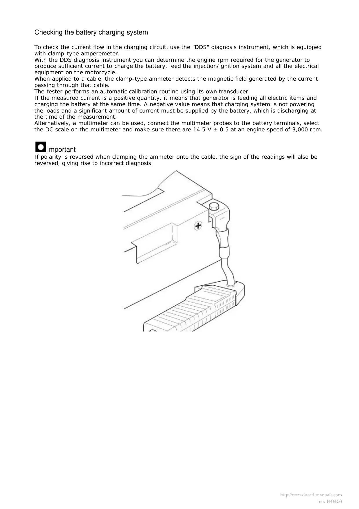
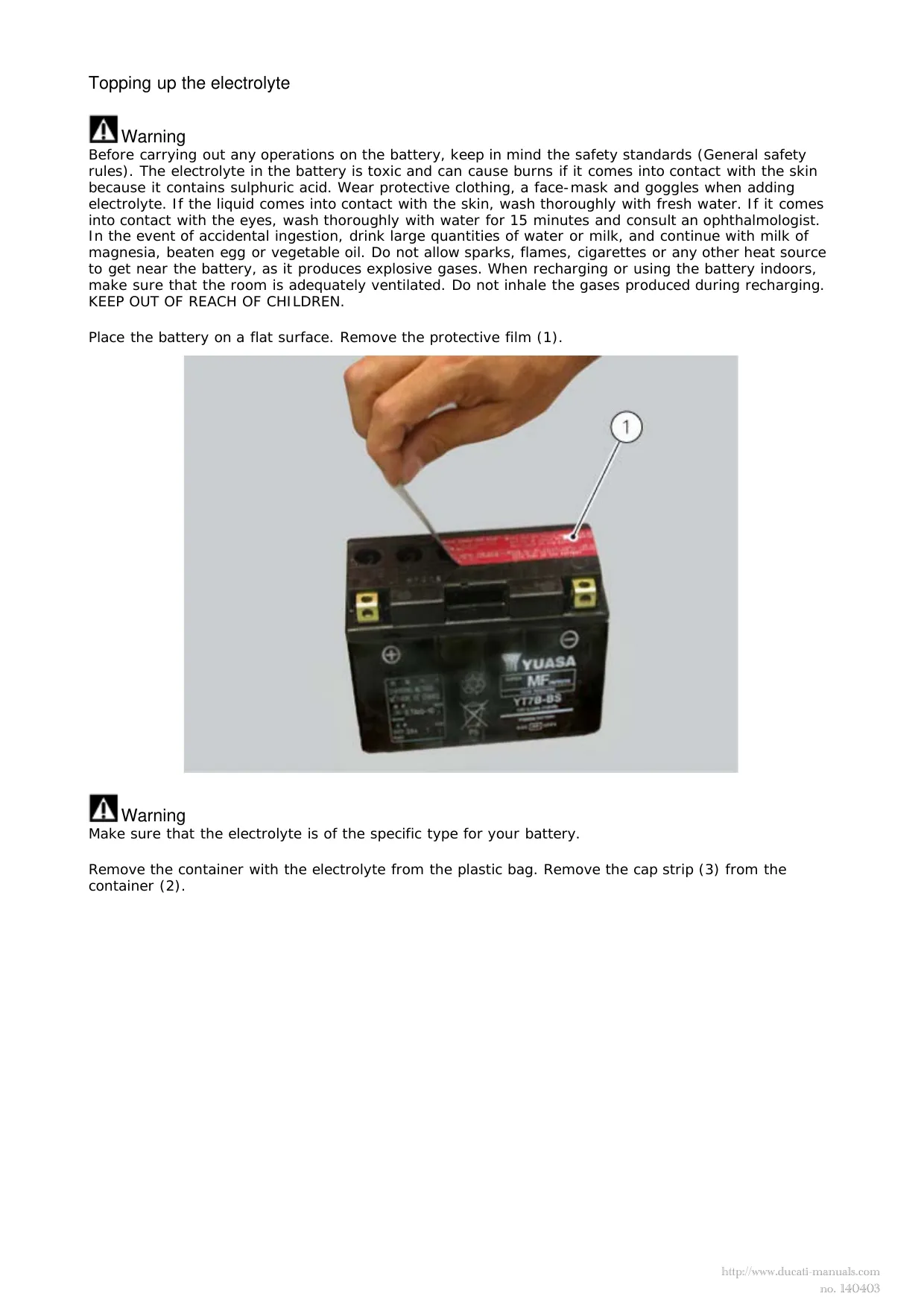
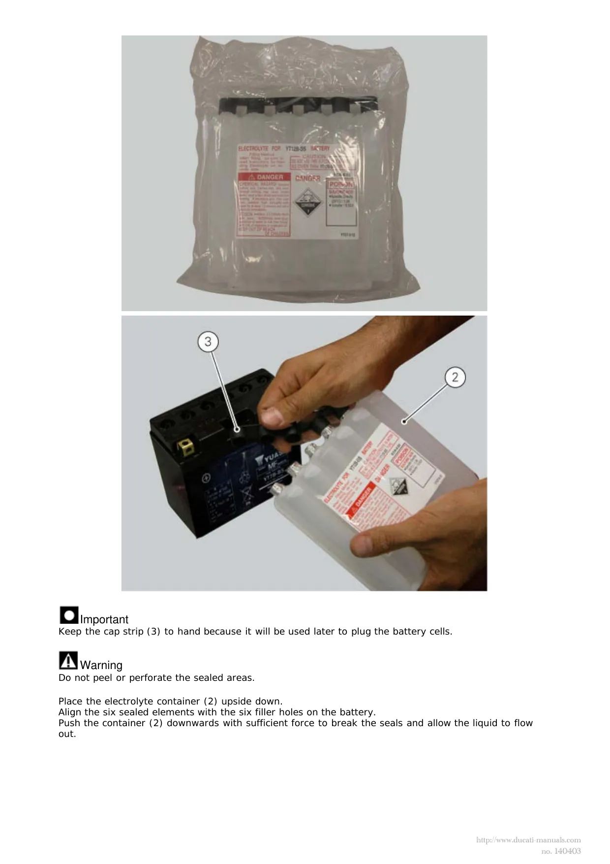
The charging-system material covers DDS clamp-ammeter testing, multimeter checks, generator output testing, and rectifier-regulator removal and installation. Battery coverage distinguishes initial electrolyte filling from care of the sealed, maintenance-free battery. Starter-motor no-load testing and starter-solenoid replacement are included, along with bulb replacement and headlight aiming.
The manual identifies Marelli 7SM engine management and documents removal and installation of the ride-by-wire throttle bodies, injectors, and fuel-pump assembly. Related repair sections cover the secondary-air system, exhaust-valve control cable, and USA evaporative-emissions canister.
For connector location and cable placement, harness-routing Table X identifies the engine-control, vehicle-control, and fuel-pump connections. Table Z locates the BBS vehicle control unit, diagnostic connector, starter wiring, and rear fuse box. The separate USA injection/electrical schematic supplies pin labels and a numbered component key.
One charging-system warning is especially important: disconnecting the battery while the engine is running can permanently damage the regulator.
ABS Diagnosis and Chassis Repair Limits
DDS diagnostic pages distinguish stored from current-session ABS faults and list wheel-speed, power-supply, pump, and valve-related checks. The ABS hydraulic-system diagram explains the inlet and outlet valves, pump, and accumulators. Diagnostic access is described for fault finding, not for changing ABS operating parameters.
Suspension coverage centers on removal, installation, and external adjustment rather than internal fork or shock rebuilding. The brake sections limit master-cylinder and caliper service to specified external parts; the rear eccentric hub is treated as a complete replacement assembly rather than an internally rebuildable unit.
Diagnostic and Specification Data
Reference tables provide assembly clearances, wear limits, fluid capacities, electrical test criteria, and fastener-specific tightening data with lubrication or threadlocker notes. The maintenance checklist identifies DDS error-memory reading, software-version checks, and service-indicator reset among the scheduled tasks.
Follow the manual’s procedure-specific electrical isolation, battery-handling, and brake-system safety precautions before carrying out repair work.
Customer Reviews
Read what our customers say about this Ducati Bike manual and share your own experience.