2003 Nissan Altima L31 series AT Automatic Transaxle manual

2003 Nissan Altima L31 series AT Automatic Transaxle manual Preview image 1
2003 Nissan Altima L31 series AT Automatic Transaxle manual Preview image 2
2003 Nissan Altima L31 series AT Automatic Transaxle manual Preview image 3
2003 Nissan Altima L31 series AT Automatic Transaxle manual Preview image 4
2003 Nissan Altima L31 series AT Automatic Transaxle manual Preview image 5
$7.99 (incl. VAT) - Instant Download
OR

File Specifications

  • File Size: 46.24 MB
  • File Type: ZIP
  • Language: English
  • Pages: Pages: 2001+ ,
  • Printable: Yes
  • Estimated Download Time: 0.95 Minutes
verified_user
Lifetime Guarantee
Re-download anytime
flash_on
Instant Download
Get it immediately
lock
Secure Payment
PayPal & Bitcoin

Models Covered in this Manual

Altima L31 series / Nissan Motor Corporation, Ltd

  • Nissan Altima L31 Base
  • Nissan Altima L31 S
  • Nissan Altima L31 SE
  • Nissan Altima L31 SL

Production/model years: 2003

Product Information

Table of Contents

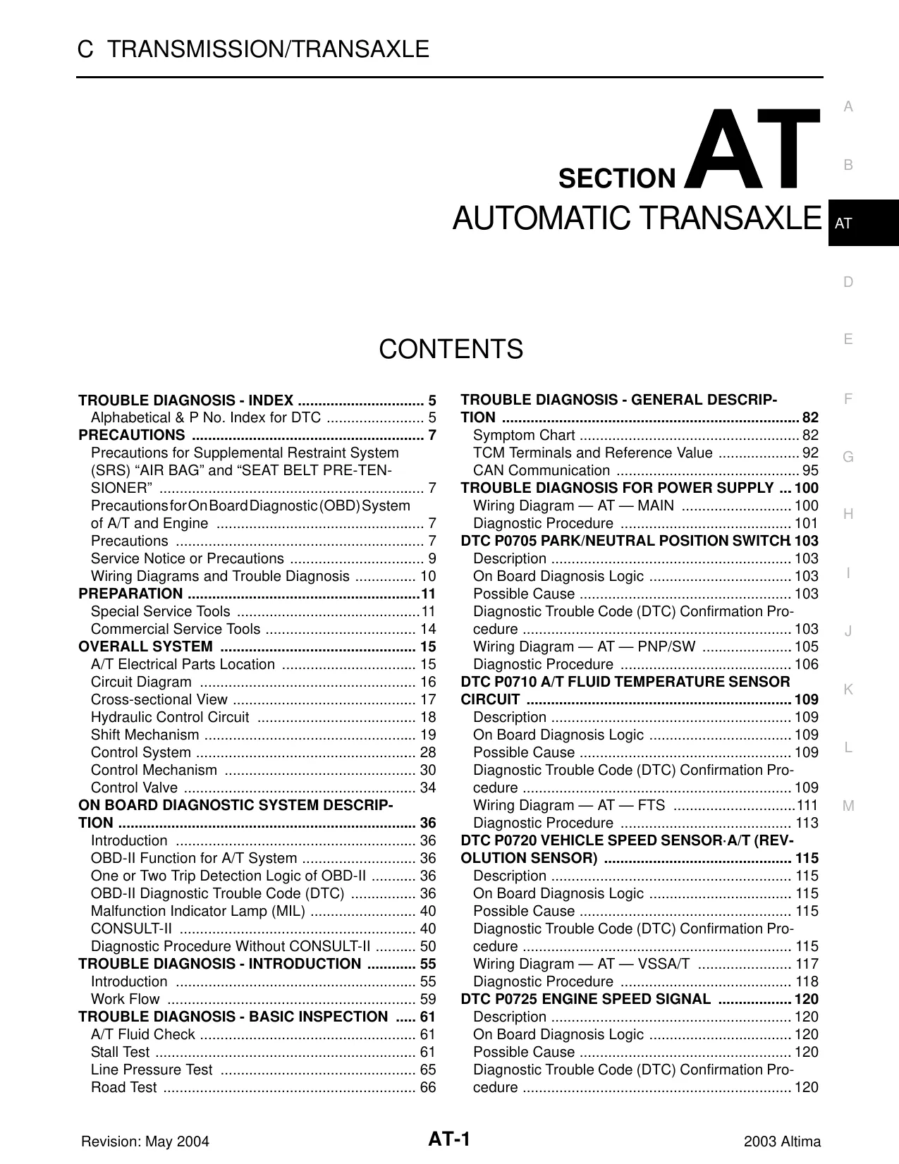
Section AT: Automatic Transaxle

  • Trouble Diagnosis - Index

    • Alphabetical & P No. Index for DTC (Page 5)
  • Precautions

    • Precautions (Page 7)
    • Precautions for Supplemental Restraint System (SRS) “Air Bag” and “Seat Belt Pre-Tensioner” (Page 7)
    • Precautions for OnBoard Diagnostic (OBD) System of A/T and Engine (Page 7)
    • Service Notice or Precautions (Page 9)
    • Wiring Diagrams and Trouble Diagnosis (Page 10)
  • Preparation

    • Special Service Tools (Page 11)
    • Commercial Service Tools (Page 14)
  • Overall System

    • A/T Electrical Parts Location (Page 15)
    • Circuit Diagram (Page 16)
    • Cross-Sectional View (Page 17)
    • Hydraulic Control Circuit (Page 18)
    • Shift Mechanism (Page 19)
    • Control System (Page 28)
    • Control Mechanism (Page 30)
    • Control Valve (Page 30)
  • On Board Diagnostic System Description

    • Introduction (Page 36)
    • OBD-II Function for A/T System (Page 36)
    • One or Two Trip Detection Logic of OBD-II (Page 36)
    • OBD-II Diagnostic Trouble Code (DTC) (Page 36)
    • Malfunction Indicator Lamp (MIL) (Page 40)
    • CONSULT-II (Page 40)
    • Diagnostic Procedure Without CONSULT-II (Page 50)
  • Trouble Diagnosis - Introduction

    • Introduction (Page 55)
    • Work Flow (Page 59)
  • Trouble Diagnosis - Basic Inspection

    • A/T Fluid Check (Page 61)
    • Stall Test (Page 61)
    • Line Pressure Test (Page 65)
    • Road Test (Page 66)
  • Trouble Diagnosis - General Description

    • Symptom Chart (Page 82)
    • TCM Terminals and Reference Value (Page 92)
    • CAN Communication (Page 95)
  • Trouble Diagnosis for Power Supply

    • Wiring Diagram — AT — Main (Page 100)
    • Diagnostic Procedure (Page 101)
  • DTC P0705 Park/Neutral Position Switch

    • Description (Page 103)
    • On Board Diagnosis Logic (Page 103)
    • Possible Cause (Page 103)
    • Diagnostic Trouble Code (DTC) Confirmation Procedure (Page 103)
    • Wiring Diagram — AT — PNP/SW (Page 105)
    • Diagnostic Procedure (Page 106)
  • DTC P0710 A/T Fluid Temperature Sensor Circuit

    • Description (Page 109)
    • On Board Diagnosis Logic (Page 109)
    • Possible Cause (Page 109)
    • Diagnostic Trouble Code (DTC) Confirmation Procedure (Page 109)
    • Wiring Diagram — AT — FTS (Page 113)
    • Diagnostic Procedure (Page 114)
  • DTC P0720 Vehicle Speed Sensor-A/T (Revolution Sensor)

    • Description (Page 115)
    • On Board Diagnosis Logic (Page 115)
    • Possible Cause (Page 115)
    • Diagnostic Trouble Code (DTC) Confirmation Procedure (Page 115)
    • Wiring Diagram — AT — VSS/A/T (Page 117)
    • Diagnostic Procedure (Page 118)
  • DTC P0725 Engine Speed Signal

    • Description (Page 120)
    • On Board Diagnosis Logic (Page 120)
    • Possible Cause (Page 120)
    • Diagnostic Trouble Code (DTC) Confirmation Procedure (Page 120)
    • Wiring Diagram — AT — ENGS (Page 121)
    • Diagnostic Procedure (Page 122)
  • DTC P0731 A/T 1st Gear Function

    • Description (Page 124)
    • On Board Diagnosis Logic (Page 124)
    • Possible Cause (Page 124)
    • Diagnostic Trouble Code (DTC) Confirmation Procedure (Page 124)
    • Wiring Diagram — AT — 1ST (Page 126)
    • Diagnostic Procedure (Page 127)
  • DTC P0732 A/T 2nd Gear Function

    • Description (Page 129)
    • On Board Diagnosis Logic (Page 129)
    • Possible Cause (Page 129)
    • Diagnostic Trouble Code (DTC) Confirmation Procedure (Page 129)
    • Wiring Diagram — AT — 2ND (Page 131)
    • Diagnostic Procedure (Page 132)
  • DTC P0733 A/T 3rd Gear Function

    • Description (Page 134)
    • On Board Diagnosis Logic (Page 134)
    • Possible Cause (Page 134)
    • Diagnostic Trouble Code (DTC) Confirmation Procedure (Page 134)
    • Wiring Diagram — AT — 3RD (Page 136)
    • Diagnostic Procedure (Page 137)
  • DTC P0734 A/T 4th Gear Function

    • Description (Page 139)
    • On Board Diagnosis Logic (Page 139)
    • Possible Cause (Page 139)
    • Diagnostic Trouble Code (DTC) Confirmation Procedure (Page 139)
    • Wiring Diagram — AT — 4TH (Page 141)
    • Diagnostic Procedure (Page 142)
  • DTC P0740 Torque Converter Clutch Solenoid Valve

    • Description (Page 146)
    • On Board Diagnosis Logic (Page 146)
    • Possible Cause (Page 146)
    • Diagnostic Trouble Code (DTC) Confirmation Procedure (Page 146)
    • Wiring Diagram — AT — TCV (Page 148)
    • Diagnostic Procedure (Page 149)
  • DTC P0744 A/T TCC S/V Function (Lock-Up)

    • Description (Page 151)
    • On Board Diagnosis Logic (Page 151)
    • Possible Cause (Page 151)
    • Diagnostic Trouble Code (DTC) Confirmation Procedure (Page 151)
    • Wiring Diagram — AT — TCCSIG (Page 153)
    • Diagnostic Procedure (Page 154)
  • DTC P0745 Line Pressure Solenoid Valve

    • Description (Page 159)
    • On Board Diagnosis Logic (Page 159)
    • Possible Cause (Page 159)
    • Diagnostic Trouble Code (DTC) Confirmation Procedure (Page 159)
    • Wiring Diagram — AT — LPSV (Page 161)
    • Diagnostic Procedure (Page 162)
  • DTC P0750 Shift Solenoid Valve A

    • Description (Page 165)
    • On Board Diagnosis Logic (Page 165)
    • Possible Cause (Page 165)
    • Diagnostic Trouble Code (DTC) Confirmation Procedure (Page 165)
    • Wiring Diagram — AT — SSV/A (Page 167)
    • Diagnostic Procedure (Page 168)
  • DTC P0755 Shift Solenoid Valve B

    • Description (Page 170)
    • On Board Diagnosis Logic (Page 170)
    • Possible Cause (Page 170)
    • Diagnostic Trouble Code (DTC) Confirmation Procedure (Page 170)
    • Wiring Diagram — AT — SSV/B (Page 172)
    • Diagnostic Procedure (Page 173)
  • DTC P1715 Throttle Position Sensor (Accelerator Pedal Position (APP) Sensor)

    • Description (Page 175)
    • On Board Diagnosis Logic (Page 175)
    • Possible Cause (Page 175)
    • Diagnostic Trouble Code (DTC) Confirmation Procedure (Page 176)
    • Wiring Diagram — AT — TPS (Page 178)
    • Diagnostic Procedure (Page 179)
  • DTC P1760 Overrun Clutch Solenoid Valve

    • Description (Page 181)
    • On Board Diagnosis Logic (Page 181)
    • Possible Cause (Page 181)
    • Diagnostic Trouble Code (DTC) Confirmation Procedure (Page 181)
    • Wiring Diagram — AT — OVRC/SV (Page 183)
    • Diagnostic Procedure (Page 187)
  • DTC U1000 CAN Communication Line

    • Description (Page 186)
    • On Board Diagnosis Logic (Page 186)
    • Possible Cause (Page 186)
    • Diagnostic Trouble Code (DTC) Confirmation Procedure (Page 186)
    • Wiring Diagram — AT — CAN (Page 188)
    • Diagnostic Procedure (Page 188)
  • DTC Batt/Fluid Temp Sen (A/T Fluid Temp Sensor Circuit and TCM Power Source)

    • Description (Page 189)
    • On Board Diagnosis Logic (Page 189)
    • Possible Cause (Page 189)
    • Diagnostic Trouble Code (DTC) Confirmation Procedure (Page 189)
    • Wiring Diagram — AT — BA/FTS (Page 191)
    • Diagnostic Procedure (Page 192)
  • DTC Vehicle Speed Sensor MTR

    • Description (Page 196)
    • On Board Diagnosis Logic (Page 196)
    • Possible Cause (Page 196)
    • Diagnostic Trouble Code (DTC) Confirmation Procedure (Page 196)
    • Wiring Diagram — AT — VSSMTR (Page 197)
    • Diagnostic Procedure (Page 199)
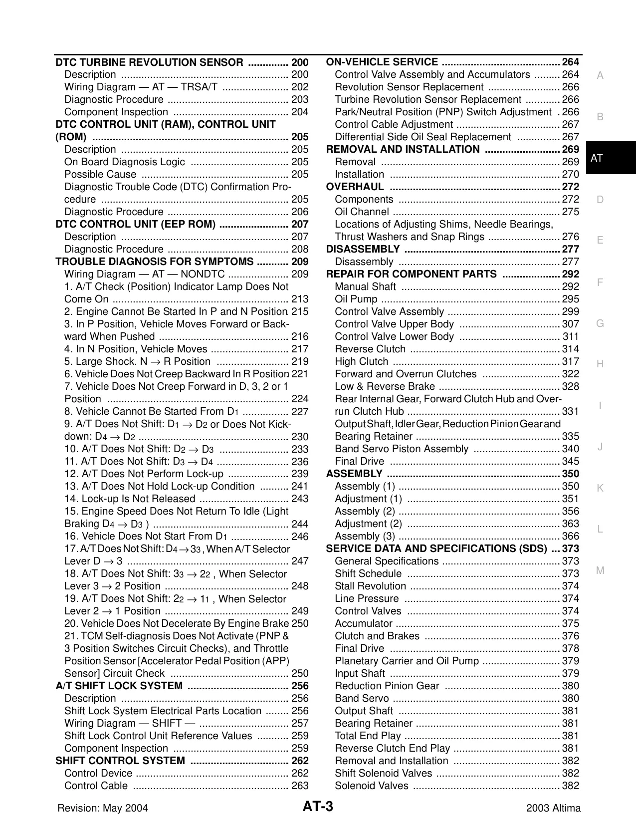
  • DTC Turbine Revolution Sensor

    • Description (Page 200)
    • Wiring Diagram — AT — TRS/A/T (Page 202)
    • Diagnostic Procedure (Page 203)
    • Component Inspection (Page 204)
  • DTC Control Unit (RAM), Control Unit (ROM)

    • Description (Page 205)
    • On Board Diagnosis Logic (Page 205)
    • Possible Cause (Page 205)
    • Diagnostic Trouble Code (DTC) Confirmation Procedure (Page 205)
    • Diagnostic Procedure (Page 206)
  • DTC Control Unit (EEP ROM)

    • Description (Page 207)
    • Diagnostic Procedure (Page 207)
  • Trouble Diagnosis for Symptoms

    • Wiring Diagram — AT — NONDTC (Page 209)
    • A/T Check (Position) Indicator Lamp Does Not Come On (Page 213)
    • Engine Cannot Be Started In P and N Positions (Page 215)
    • In P Position, Vehicle Moves Forward or Backward When Pushed (Page 216)
    • In N Position, Vehicle Moves Forward (Page 217)
    • Large Shock, N → P Position (Page 219)
    • Vehicle Does Not Creep Backward In R Position (Page 221)
    • Vehicle Does Not Move Forward In D, 3, 2, or 1 (Page 222)
    • A/T Does Not Shift: D1 → D2 or Does Not Kick-Down: D4 → D2 (Page 227)
    • A/T Does Not Shift: D2 → D3 (Page 230)
    • A/T Does Not Shift: D3 → D4 (Page 236)
    • A/T Does Not Perform Lock-Up (Page 239)
    • A/T Does Not Hold Lock-Up Condition (Page 241)
    • A/T Is Not Released (Page 243)
    • Engine Speed Does Not Return To Idle (Page 244)
    • Vehicle Does Not Start From D1 (Page 246)
    • A/T Does Not Shift: D4 → 3 → 2 (Page 247)
    • A/T Does Not Shift: 3 → 2 → 1 (Page 248)
    • Vehicle Does Not Decelerate By Engine Brake (Page 250)
    • TCM Self-Diagnosis Does Not Activate (Page 250)
  • A/T Shift Lock System

    • Description (Page 256)
    • Shift Lock System Electrical Parts Location (Page 256)
    • Wiring Diagram — Shift (Page 257)
    • Shift Lock Control Unit Reference Values (Page 259)
    • Component Inspection (Page 260)
  • Shift Control System

    • Control Device (Page 262)
    • Control Cable (Page 263)
  • On-Vehicle Service

    • Control Valve Assembly and Accumulators (Page 264)
    • Revolution Sensor Replacement (Page 266)
    • Turbine Revolution Sensor Replacement (Page 266)
    • Park/Neutral Position (PNP) Switch Adjustment (Page 266)
    • Control Cable Adjustment (Page 267)
    • Differential Side Oil Seal Replacement (Page 267)
  • Removal and Installation

    • Removal (Page 269)
    • Installation (Page 270)
  • Overhaul

    • Components (Page 272)
    • Oil Channel (Page 275)
    • Locations of Adjusting Shims, Needle Bearings, Thrust Washers and Snap Rings (Page 276)
  • Disassembly

    • Disassembly (Page 277)
  • Repair for Component Parts

    • Manual Shaft (Page 292)
    • Oil Pump (Page 295)
    • Control Valve Assembly (Page 299)
    • Control Valve Upper Body (Page 307)
    • Control Valve Lower Body (Page 311)
    • Reverse Clutch (Page 314)
    • High Clutch (Page 317)
    • Forward and Overrun Clutches (Page 322)
    • Low & Reverse Brake (Page 328)
    • High Clutch Gear, Forward Clutch Hub and Overrun Clutch Hub (Page 331)
    • Output Shaft, Idler Gear, Reduction Pinion Gear and Bearing Retainer (Page 335)
    • Band Servo Piston Assembly (Page 340)
    • Final Drive (Page 349)
  • Assembly

    • Assembly (1) (Page 350)
    • Assembly (2) (Page 351)
    • Assembly (3) (Page 363)
    • Assembly (4) (Page 366)
  • Service Data and Specifications (SDS)

    • General Specifications (Page 373)
    • Shift Schedule (Page 373)
    • Stall Revolution (Page 374)
    • Line Pressure (Page 374)
    • Control Valves (Page 374)
    • Accumulator (Page 375)
    • Clutch and Brakes (Page 376)
    • Final Drive (Page 378)
    • Planetary Carrier and Oil Pump (Page 379)
    • Input Shaft (Page 379)
    • Reduction Pinion Gear (Page 380)
    • Band Servo (Page 380)
    • Output Shaft (Page 381)
    • Bearing Retainer (Page 381)
    • Total End Play (Page 381)
    • Reverse Clutch End Play (Page 381)
    • Removal and Installation (Page 382)
    • Shift Solenoid Valves (Page 382)
    • Solenoid Valves (Page 382)
    • A/T Fluid Temperature Sensor (Page 382)
    • Revolution Sensor (Page 382)
    • Dropping Resistor (Page 382)
    • Turbine Revolution Sensor (Page 383)

  • The pricing of this manual, handbooks, and repair guides is determined by the seller, and prices may vary across different platforms. Please compare prices before making a purchase.
  • Many of our manuals feature comments and ratings from other users to aid in your decision-making process. After your purchase, we encourage you to leave a review to assist other users.
  • Don't hesitate to download the repair manual you need now. You will receive a lifetime guarantee for the download as outlined in our FAQs.
  • For inquiries or assistance, please use our contact form, and we will ensure your request is addressed promptly.

How to Download Your Manual - Delivery Policy

- Delivery: Download link will appear on the checkout page after your payment is complete.

Within a minute after completing the payment process, you will receive two emails from us. One for the completed payment and another with the download link. The download link is valid for 3 days.
Lifetime Guarantee

Customer Reviews

We value your feedback and would love to hear about your experience with our manual.

Add Comment

* Required information
1000
Captcha Image
Powered by Commentics

Comments

No comments yet. Be the first!