2007–2010 Suzuki RM-Z250 Factory Service Manual (P/N 99011-10H51-01A)
329 Pages • 29.58 MB • Printable PDFs (ZIP Download)
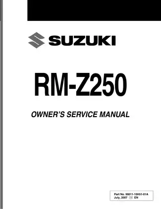
Suzuki Models Covered & Key Technical Specifications
Models: RM-Z250
Sub-models / Variants: E-03 (USA), E-19 (E.U.), E-28 (Canada), 000 (Japan)
Model Years: 2007–2010 (2007, 2008, 2009, 2010)
Serial Numbers: JS1RJ41A000 500001–, JS1RJ41C 82 100001–, JS1RJ41C000 500001–
-
Engine oil capacity (oil change): 900 ml (1.0/0.8 US/Imp qt)
-
Engine idle speed: 2 100 ± 50 r/min
-
Standard spark plug: NGK CR8EIA-10
-
Spark plug gap: 0.9 – 1.0 mm (0.035 – 0.039 in)
-
Drive chain slack: 35 – 45 mm (1.4 – 1.8 in)
-
Clutch lever play: 2 – 3 mm (0.08 – 0.12 in)
-
Throttle cable play: 2 – 4 mm (0.08 – 0.16 in)
-
Valve clearance (cold) intake: 0.09 – 0.16 mm (0.004 – 0.006 in)
-
Valve clearance (cold) exhaust: 0.17 – 0.24 mm (0.006 – 0.009 in)
-
Tire pressure (cold): 70 – 110 kPa (0.7 – 1.1 kgf/cm2, 10 – 16 psi)
Suzuki Manual Features & Content Preview
- Exact factory coverage: Suzuki RM-Z250 K8 (2008 model) Owner's Service Manual, Part No. 99011-10H51-01A, supplied as a 329-page PDF for 000 Japan, E-03 U.S., E-19 EU, and E-28 Canada specifications.
- Engine and transmission repair: Covers engine removal and installation, automatic-decompression and cam-timing work, cylinder-head and valve service, piston and ring inspection, crankcase separation, and crankshaft and transmission service.
- Keihin carburetor and CDI diagnosis: Details FCR37MX disassembly and reassembly, float and fuel-level checks, accelerator-pump timing, throttle-position-sensor setup, ignition peak-voltage and resistance tests, and no-spark fault isolation.
- Chassis and brake service: Includes wheel, bearing, seal, spoke, sprocket, and brake-disc work; brake-fluid replacement and bleeding; and front and rear caliper and master-cylinder overhaul procedures.
- Suspension service and race setup: Documents front-fork teardown and sealing, fork oil and spring changes, steering-bearing service, rear-shock oil and nitrogen service, swingarm and linkage repair, and symptom-based suspension tuning.
- Factory workshop references: Provides the wiring diagram, CDI circuit, lubrication-system chart, routing layouts, exploded assembly views, torque tables, capacities, wear limits, clearance data, pressure checks, electrical test specifications, and Suzuki special-tool numbers.
The manual moves from pre-practice and pre-race checklists and a race/hour maintenance schedule into full shop procedures. It is best suited to mechanically experienced owners and technicians comfortable with precision measuring equipment and model-specific service tools. Suzuki specifically advises riders unfamiliar with Keihin carburetor operation and jetting to have an authorized dealer perform those alterations.
K8 Market and Frame Coverage
The country table identifies 000 (Japan) beginning with frame No. JS1RJ41A000 500001, E-19 (EU) beginning with JS1RJ41C000 500001, and E-03 (U.S.) and E-28 (Canada) beginning with the manual's printed JS1RJ41C 82 100001 sequence. The publication is K8-specific; it is not a 2007-2010 multi-year service manual.
Market differences continue into the fuel data. The FCR37MX carburetor table separates E-03 carburetor ID 10H2 from E-19/E-28 ID 10H3, with different factory main-jet, jet-needle/clip, pilot-screw, and leak-jet specifications. This is carburetor and throttle-position-sensor coverage, not an EFI repair section.
Engine, Drivetrain, and Fuel-System Repair
Top-end repair coverage runs from the cylinder-head cover and camshafts through the automatic decompression mechanism, cam chain and tensioner, valves, guides, seats, cylinder, piston, and rings. Inspection procedures use bore gauges, micrometers, dial gauges, and Plastigauge, with separate intake and exhaust tappet-shim selection charts for valve-clearance adjustment.
Bottom-end repair includes crankcase separation, crankshaft and connecting-rod inspection, five-speed transmission removal and installation, shift-fork and gear checks, bearing and oil-seal replacement, oil-pump service, and final movement checks. Separate chapters handle the clutch plates, sleeve hub and primary driven gear, clutch-release camshaft, kick starter, and gearshift linkage.
The fuel chapter goes beyond jetting tables. It covers the fuel tank and valve, carburetor teardown and cleaning, float-valve inspection, measured fuel level and float height, accelerator-pump timing, throttle-cable setup, and TPS testing and adjustment. Troubleshooting tables address hard starting, engine noise, overheating, shifting, suspension, brake, and no-spark complaints.
Suspension, Brakes, and Chassis
The fork section covers tube and seal service, damper-oil filling, reassembly, installation, and post-repair inspection. The damper-rod assembly and compression-damper unit are serviced only as complete assemblies; the manual warns against internal disassembly. Rear suspension coverage includes spring replacement, shock oil service, nitrogen charging, damper-rod inspection, swingarm service, and linkage bearing replacement.
The fork chapter warns that grease used in place of fork oil on the seals can collect dirt, damage the seal lips, and cause leakage. Incorrect rear-linkage bolt or shock orientation can interfere with suspension movement and damage the linkage.
Brake repair covers fluid replacement and air bleeding, pad and disc inspection, caliper piston and seal service, and front and rear master-cylinder overhaul. Wheel chapters add axle and rim runout checks, bearing and dust-seal replacement, disc and rear-sprocket replacement, and rear-spoke installation.
Diagrams, Tools, and Service Data
Visual references include the full wiring diagram, CDI electrical circuit, no-spark diagnostic flowchart, engine-lubrication-system chart, exploded assembly views, and dedicated cable and hose-routing layouts. Suzuki tools are identified by number, including crankcase separator 09920-13120, crankshaft installer 09910-32812 with attachment 09911-11310, multi-circuit tester 09900-25008, front-fork oil-seal installer 09940-52861, and RCU socket wrench 09941-53660.
The final service-data section consolidates component-specific tightening torques, capacities and approved fluids, inspection limits, runout and clearance specifications, compression and oil-pressure checks, ignition and TPS test values, suspension settings, and general specifications. It also includes spare and optional parts lists plus a reusable race-setting data sheet.
Brake fluid, hot coolant, rotating engine parts, and the rear shock's pressurized nitrogen all require appropriate shop equipment and protective gear. Follow the manual's safety warnings and use a qualified repair shop for work beyond your tools or experience.
Customer Reviews
Read what our customers say about this Suzuki Bike manual and share your own experience.