2005-2008 Nissan Navara D40 AT Automatic Transmission manual

2005-2008 Nissan Navara D40 AT Automatic Transmission manual Preview image 1
2005-2008 Nissan Navara D40 AT Automatic Transmission manual Preview image 2
2005-2008 Nissan Navara D40 AT Automatic Transmission manual Preview image 3
2005-2008 Nissan Navara D40 AT Automatic Transmission manual Preview image 4
2005-2008 Nissan Navara D40 AT Automatic Transmission manual Preview image 5
$7.99 (incl. VAT) - Instant Download
OR

File Specifications

  • File Size: 42.77 MB
  • File Type: ZIP
  • Language: English
  • Printable: Yes
  • Estimated Download Time: 0.88 Minutes
verified_user
Lifetime Guarantee
Re-download anytime
flash_on
Instant Download
Get it immediately
lock
Secure Payment
PayPal & Bitcoin

Models Covered in this Manual

Navara D40, Nissan Motor Corporation, Ltd

  • 2005 Nissan Navara D40
  • 2006 Nissan Navara D40
  • 2007 Nissan Navara D40
  • 2008 Nissan Navara D40

Product Information

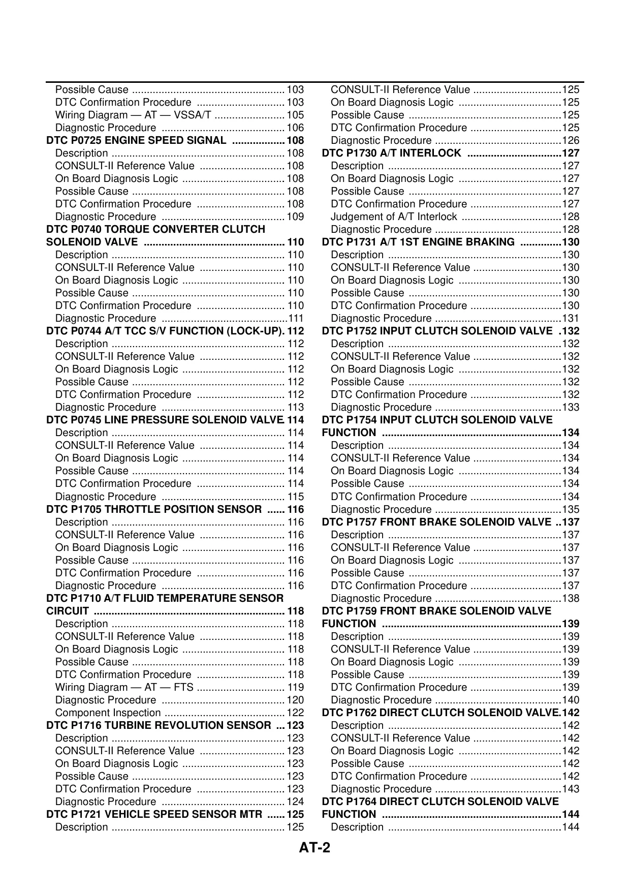
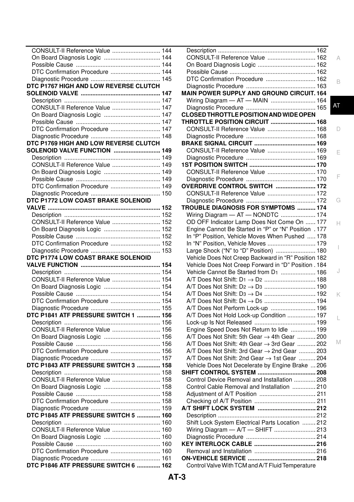
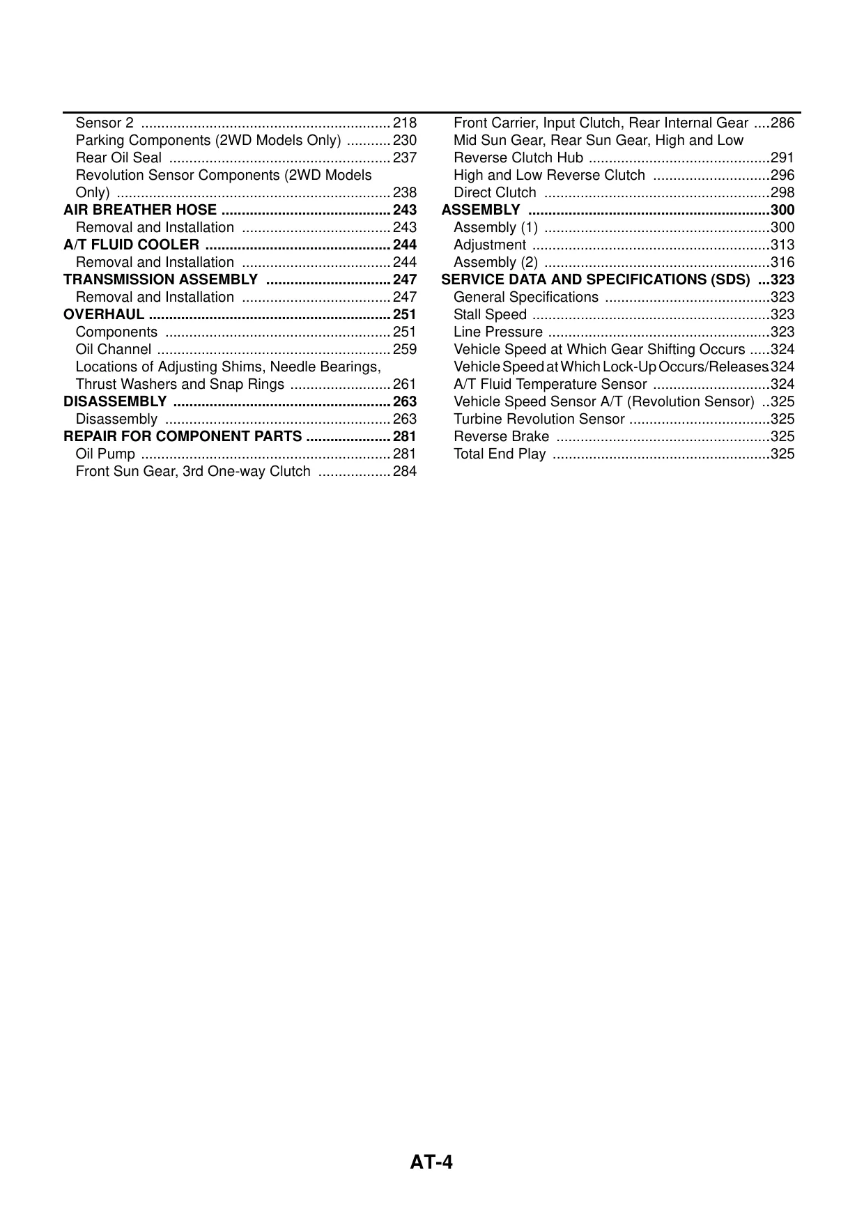
Table of Contents

INDEX FOR DTC

  • Alphabetical Index
  • DTC No. Index

PRECAUTIONS

  • Precautions for Supplemental Restraint System (SRS) "AIR BAG" and "SEAT BELT PRE-TENSIONER"
  • Precautions
  • Wiring Diagrams and Trouble Diagnosis

PREPARATION

  • Special Service Tools
  • Commercial Service Tools

A/T FLUID

  • Changing A/T Fluid
  • Checking A/T Fluid

A/T CONTROL SYSTEM

  • Cross-Sectional View (2WD Models)
  • Cross-Sectional View (4WD Models)
  • Shift Mechanism
  • TCM Function
  • CAN Communication
  • Input/Output Signal of TCM
  • Line Pressure Control
  • Shift Control
  • Lock-up Control
  • Engine Brake Control
  • Control Valve

TROUBLE DIAGNOSIS

  • DTC Inspection Priority Chart
  • Fail-safe
  • How to Perform Trouble Diagnosis for Quick and Accurate Repair
  • A/T Electrical Parts Location
  • Circuit Diagram
  • Inspections Before Trouble Diagnosis
  • Check Before Engine Is Started
  • Check at Idle
  • Cruise Test - Part 1
  • Cruise Test - Part 2
  • Cruise Test - Part 3
  • Vehicle Speed at Which Gear Shifting Occurs
  • Vehicle Speed at Which Lock-up Occurs/Releases
  • Symptom Chart
  • TCM Input/Output Signal Reference Values
  • CONSULT-II Function (A/T)
  • Diagnostic Procedure Without CONSULT-II

DTC U1000 CAN COMMUNICATION LINE

  • Description
  • On Board Diagnosis Logic
  • Possible Cause
  • DTC Confirmation Procedure
  • Wiring Diagram — AT — CAN
  • Diagnostic Procedure

DTC P0615 START SIGNAL CIRCUIT

  • Description
  • CONSULT-II Reference Value
  • On Board Diagnosis Logic
  • Possible Cause
  • DTC Confirmation Procedure
  • Wiring Diagram — AT — STSIG
  • Diagnostic Procedure

DTC P0700 TCM

  • Description
  • On Board Diagnosis Logic
  • Possible Cause
  • DTC Confirmation Procedure
  • Diagnostic Procedure

DTC P0705 PARK/NEUTRAL POSITION SWITCH

  • Description
  • CONSULT-II Reference Value
  • On Board Diagnosis Logic
  • Possible Cause
  • DTC Confirmation Procedure
  • Wiring Diagram — AT — PNP/SW
  • Diagnostic Procedure

DTC P0720 VEHICLE SPEED SENSOR A/T (REVOLUTION SENSOR)

  • Description
  • CONSULT-II Reference Value
  • On Board Diagnosis Logic
  • Possible Cause
  • DTC Confirmation Procedure
  • Wiring Diagram — AT — VSSAT
  • Diagnostic Procedure

DTC P0725 ENGINE SPEED SIGNAL

  • Description
  • CONSULT-II Reference Value
  • On Board Diagnosis Logic
  • Possible Cause
  • DTC Confirmation Procedure
  • Diagnostic Procedure

DTC P1730 A/T INTERLOCK

  • Description
  • On Board Diagnosis Logic
  • Possible Cause
  • DTC Confirmation Procedure
  • Judgement of A/T Interlock
  • Diagnostic Procedure

DTC P1731 A/T 1ST ENGINE BRAKING

  • Description
  • CONSULT-II Reference Value
  • On Board Diagnosis Logic
  • Possible Cause
  • DTC Confirmation Procedure
  • Diagnostic Procedure

DTC P1752 INPUT CLUTCH SOLENOID VALVE

  • Description
  • CONSULT-II Reference Value
  • On Board Diagnosis Logic
  • Possible Cause
  • DTC Confirmation Procedure
  • Diagnostic Procedure

DTC P1754 INPUT CLUTCH SOLENOID VALVE FUNCTION

  • Description
  • CONSULT-II Reference Value
  • On Board Diagnosis Logic
  • Possible Cause
  • DTC Confirmation Procedure
  • Diagnostic Procedure

DTC P1757 FRONT BRAKE SOLENOID VALVE

  • Description
  • CONSULT-II Reference Value
  • On Board Diagnosis Logic
  • Possible Cause
  • DTC Confirmation Procedure
  • Diagnostic Procedure

DTC P1759 FRONT BRAKE SOLENOID VALVE FUNCTION

  • Description
  • CONSULT-II Reference Value
  • On Board Diagnosis Logic
  • Possible Cause
  • DTC Confirmation Procedure
  • Diagnostic Procedure

DTC P1762 DIRECT CLUTCH SOLENOID VALVE

  • Description
  • CONSULT-II Reference Value
  • On Board Diagnosis Logic
  • Possible Cause
  • DTC Confirmation Procedure
  • Diagnostic Procedure

DTC P1764 DIRECT CLUTCH SOLENOID VALVE FUNCTION

  • Description
  • CONSULT-II Reference Value
  • On Board Diagnosis Logic
  • Possible Cause
  • DTC Confirmation Procedure
  • Diagnostic Procedure

DTC P1767 HIGH AND LOW REVERSE CLUTCH SOLENOID VALVE

  • Description
  • CONSULT-II Reference Value
  • On Board Diagnosis Logic
  • Possible Cause
  • DTC Confirmation Procedure
  • Diagnostic Procedure

DTC P1769 HIGH AND LOW REVERSE CLUTCH SOLENOID VALVE FUNCTION

  • Description
  • CONSULT-II Reference Value
  • On Board Diagnosis Logic
  • Possible Cause
  • DTC Confirmation Procedure
  • Diagnostic Procedure

DTC P1772 LOW COAST BRAKE SOLENOID VALVE

  • Description
  • CONSULT-II Reference Value
  • On Board Diagnosis Logic
  • Possible Cause
  • DTC Confirmation Procedure
  • Diagnostic Procedure

DTC P1774 LOW COAST BRAKE SOLENOID VALVE FUNCTION

  • Description
  • CONSULT-II Reference Value
  • On Board Diagnosis Logic
  • Possible Cause
  • DTC Confirmation Procedure
  • Diagnostic Procedure

DTC P1841 ATF PRESSURE SWITCH 1

  • Description
  • CONSULT-II Reference Value
  • On Board Diagnosis Logic
  • Possible Cause
  • DTC Confirmation Procedure
  • Diagnostic Procedure

DTC P1843 ATF PRESSURE SWITCH 3

  • Description
  • CONSULT-II Reference Value
  • On Board Diagnosis Logic
  • Possible Cause
  • DTC Confirmation Procedure
  • Diagnostic Procedure

DTC P1845 ATF PRESSURE SWITCH 5

  • Description
  • CONSULT-II Reference Value
  • On Board Diagnosis Logic
  • Possible Cause
  • DTC Confirmation Procedure
  • Diagnostic Procedure

DTC P1846 ATF PRESSURE SWITCH 6

  • Description
  • CONSULT-II Reference Value
  • On Board Diagnosis Logic
  • Possible Cause
  • DTC Confirmation Procedure
  • Diagnostic Procedure

MAIN POWER SUPPLY AND GROUND CIRCUIT

  • Wiring Diagram — AT — MAIN
  • Diagnostic Procedure

THROTTLE POSITION CIRCUIT

  • Throttle Position Circuit
  • CONSULT-II Reference Value
  • Diagnostic Procedure

BRAKE SIGNAL CIRCUIT

  • CONSULT-II Reference Value
  • Diagnostic Procedure

1ST POSITION SWITCH

  • CONSULT-II Reference Value
  • Diagnostic Procedure

OVERDRIVE CONTROL SWITCH

  • CONSULT-II Reference Value
  • Diagnostic Procedure

TROUBLE DIAGNOSIS FOR SYMPTOMS

  • Wiring Diagram — AT — NONDTC
  • OD OFF Indicator Lamp Does Not Come On
  • Engine Cannot Be Started in "P" or "N" Position
  • In "P" Position, Vehicle Moves When Pushed
  • In "N" Position, Vehicle Moves
  • Large Shock ("N" to "D" Position)
  • Vehicle Does Not Creep Backward in "R" Position
  • Vehicle Does Not Creep Forward in "D" Position
  • Vehicle Cannot Be Started from D1
  • A/T Does Not Shift: D1 -> D2
  • A/T Does Not Shift: D2 -> D3
  • A/T Does Not Shift: D3 -> D4
  • A/T Does Not Shift: D4 -> D5
  • A/T Does Not Perform Lock-up
  • A/T Does Not Hold Lock-up Condition
  • Lock-up Is Not Released
  • Engine Speed Does Not Return to Idle
  • A/T Does Not Shift: 5th Gear -> 4th Gear
  • A/T Does Not Shift: 4th Gear -> 3rd Gear
  • A/T Does Not Shift: 3rd Gear -> 2nd Gear
  • A/T Does Not Shift: 2nd Gear -> 1st Gear
  • Vehicle Does Not Decelerate by Engine Brake

SHIFT CONTROL SYSTEM

  • Control Device Removal and Installation
  • Control Cable Removal and Installation
  • Adjustment of A/T Position
  • Checking of A/T Position

A/T SHIFT LOCK SYSTEM

  • Description
  • Shift Lock System Electrical Parts Location
  • Wiring Diagram — AT — SHIFT
  • Diagnostic Procedure

KEY INTERLOCK CABLE

  • Removal and Installation

ON-VEHICLE SERVICE

  • Control Valve With TCM and A/T Fluid Temperature Sensor
  • Sensor 2
  • Parking Components (2WD Models Only)
  • Rear Oil Seal
  • Revolution Sensor Components (2WD Models Only)
  • Air Breather Hose
  • Removal and Installation
  • A/T Fluid Cooler
  • Removal and Installation

TRANSMISSION ASSEMBLY

  • Removal and Installation

OVERHAUL

  • Components
  • Oil Channel
  • Locations of Adjusting Shims, Needle Bearings, Thrust Washers and Snap Rings

DISASSEMBLY

  • Disassembly

REPAIR FOR COMPONENT PARTS

  • Oil Pump
  • Front Sun Gear, 3rd One-way Clutch
  • Front Carrier, Input Clutch, Rear Internal Gear
  • Mid Sun Gear, Rear Sun Gear, High and Low
  • Reverse Clutch Hub
  • High and Low Reverse Clutch
  • Direct Clutch

ASSEMBLY

  • Assembly (1)
  • Adjustment
  • Assembly (2)

SERVICE DATA AND SPECIFICATIONS (SDS)

  • General Specifications
  • Stall Speed
  • Line Pressure
  • Vehicle Speed at Which Gear Shifting Occurs
  • Vehicle Speed at Which Lock-Up Occurs/Releases
  • A/T Fluid Temperature Sensor
  • Vehicle Speed Sensor A/T (Revolution Sensor)
  • Turbine Revolution Sensor
  • Reverse Brake
  • Total End Play

  • The price of the manual is set by the seller, so it may vary on different pages. Please compare prices before purchasing.
  • Comments and ratings from other users are available to help with your decision, and leaving a review after your purchase can assist other users.
  • The download comes with a lifetime guarantee as described in the FAQs, and any inquiries can be directed to the seller through the contact form provided.

How to Download Your Manual - Delivery Policy

**Instant delivery:** Your download link will appear on the checkout page after your payment is complete.

Within a minute after completing the payment process, you will receive two emails from us. One for the completed payment and another with the download link. The download link is valid for 3 days.
Lifetime Guarantee

Customer Reviews

We value your feedback and would love to hear about your experience with our manual.

Add Comment

* Required information
1000
Captcha Image
Powered by Commentics

Comments

No comments yet. Be the first!