1999-2001 Isuzu NKR, NPR, NQR ABS Workshop Manual
Field service reference for Isuzu NKR, NPR, NQR Anti-Lock Brake System (ABS) diagnostic procedures, troubleshooting, and component information. Abe008
Manual Preview
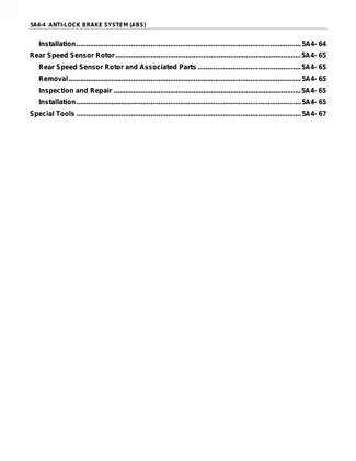
Sample pages from the 1999-2001 Isuzu NKR, NPR, NQR ABS Workshop Manual manual

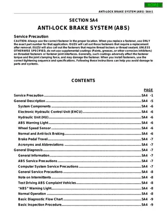
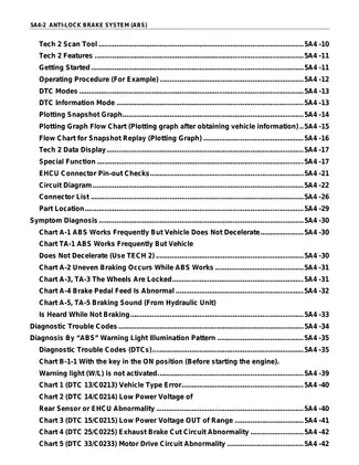
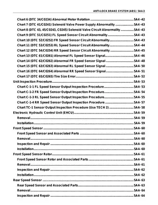
Purchase & Download
Models Covered & Key Technical Specifications
1999-2001 Isuzu NKR, NPR, NQR ABS Workshop Manual
Anti-Lock Brake System (ABS) Manual | Reference Documentation
- Approved Thermal Envelope: 15-30C defines the operational limit Framework.
- Baseline RPM Specs: 500 RPM signifies the minimum operational speed Parameters.
- Primary Physical Specs: 2550 mm is the overall vehicle length Topology.
- General Coupling Torques: 30 N-m -- signifies the torque for wheel speed sensor mounting Bounds.
- Certified System Fill: 1.5 L is the brake fluid capacity Matrix.
- Reference Cooling Specs: For optimal operation, 20 C represents the ambient temperature Standards.
Professional Workshop Service Manual & Technical Specifications
Reference-Grade Training Diagnostic Manual: Truck Manual for Isuzu NKR, NPR, NQR, covers 1999-01 Manual-Nexus
Asset-ID: 1999-2001 Isuzu ABS Manual // Design-Core: Truck / Anti-Lock Brake System Logic // Asset-ID: Workshop Manual.
Safely requiring
| Identifier | Value | Calibration-Standards |
|---|---|---|
| Front Speed Sensor | 22 N·m | 2.2kgf·m/16lb·ft |
| Rear Speed Sensor | 18 N·m | 1.8kgf·m/13lb·ft |
| ABS EHCU | 0-0.3V | Not specified |
Providing a structural breakdown of:
- Contents
- System Components
- Diagnostic Trouble Codes (DTCs)
- Symptom Diagnosis
- Unit Inspection Procedure
Introduction This manual details the Anti-lock Brake System (ABS) for Isuzu NKR, NPR, and NQR trucks from 1999 to 2001. It covers system description, components, diagnosis, and inspection procedures.
System Overview
The Anti-lock Brake System (ABS) is designed to prevent wheel lock-up during braking, enhancing vehicle control. It comprises the Electronic Hydraulic Control Unit (EHCU), four wheel speed sensors, and an ABS warning light.
Diagnostic Procedures
The manual outlines diagnostic steps based on symptoms and Diagnostic Trouble Codes (DTCs). It includes flowcharts and specific tests, such as those using the Tech 2 scan tool, to pinpoint malfunctions.
Inspection and Repair
Detailed inspection procedures for components like speed sensors, EHCU, and related circuits are provided. This ensures correct diagnosis and repair of ABS issues.
This manual documents torque specifications for the wheel speed sensors to ensure proper assembly.
FAQ
Customer Reviews
Read what our customers say about this Isuzu Truck manual and share your own experience.
Add a Review
This policy contains information about your privacy. By posting, you are declaring that you understand this policy:
- Your name, rating, website address, town, country, state and comment will be publicly displayed if entered.
- Aside from the data entered into these form fields, other stored data about your comment will include:
- Your IP address (not displayed)
- The time/date of your submission (displayed)
- Your email address will not be shared. It is collected for only two reasons:
- Administrative purposes, should a need to contact you arise.
- To inform you of new comments, should you subscribe to receive notifications.
- A cookie may be set on your computer. This is used to remember your inputs. It will expire by itself.
This policy is subject to change at any time and without notice.
These terms and conditions contain rules about posting comments. By submitting a comment, you are declaring that you agree with these rules:
- Although the administrator will attempt to moderate comments, it is impossible for every comment to have been moderated at any given time.
- You acknowledge that all comments express the views and opinions of the original author and not those of the administrator.
- You agree not to post any material which is knowingly false, obscene, hateful, threatening, harassing or invasive of a person's privacy.
- The administrator has the right to edit, move or remove any comment for any reason and without notice.
Failure to comply with these rules may result in being banned from submitting further comments.
These terms and conditions are subject to change at any time and without notice.
Reviews (2)