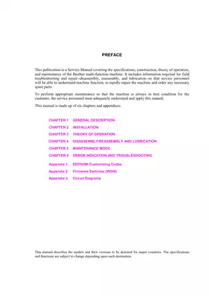
2001 Brother MFC6800/DCP1000/MFC9180/MFC9160 Service Manual
Complete service documentation for Brother multifunction machines covering laser printing, CCD scanning, fax transmission, and all hardware diagnostics with component-level repair procedures and parts specifications.
Manual Preview

Sample pages from the 2001 Brother MFC6800/DCP1000/MFC9180/MFC9160 Service Manual manual


Purchase & Download
Models Covered & Key Technical Specifications
Brother MFC-6800, DCP-1000, MFC-9180, MFC-9160 — 2001 Documentary Advanced Portfolio | Service Manual Package.
- System Package Size: 459 x 458 x 354 mm (18.1 x 18.0 x 13.9 in) is standardized to the external machine dimension Benchmarks.
- Maximum Native Resolution: For optimal scanning performance, 600 x 300 dpi is calibrated to the optical CCD sensor output Range.
- Measured Threaded Fastener Data: 0.39–0.98 N·m (4–10 kgf·cm) — determines the assembly screw tightening torque Sequences.
- Published Alignment Specs: The drum unit requires 20,000 pages at 5% coverage for continuous print cycle longevity Baseline.
- Authorized Thermal Limits: Operating temperature achieves 10–32.5°C (50–90.5°F) environmental boundary Requirements.
- Technical Net Mass: Machine weight corresponds to 11 kg (24.2 lb) without consumables installed Threshold.
Professional Workshop Service Manual & Technical Specifications
Applied Manual: Brother 2001 MFC6800 / DCP1000 / MFC9180 / MFC9160 Hydraulic-Guide
Procedure-Type: MFC-6800, DCP-1000, MFC-9180, MFC-9160 — Multifunction Laser Systems // Engine-Type: Copier/Facsimile/Scanner Combined Operations Logic // Technical-Domain: Complete Field Service and Component Reference Documentation.
| Document Section | Coverage | Reference Source |
|---|---|---|
| Machine Overview | Four copier models with laser printing, facsimile transmission, and scanning capabilities | Chapters 1-3 |
| Installation & Maintenance Protocol | Flash ROM updates, ID code configuration, and firmware customization | Chapter 2, Appendices 1-2 |
| System Architecture | Scanner mechanism, laser printing process, sensor arrays, and control electronics | Chapter 3 |
The manual presents information on general machine description covering external dimensions (459 x 458 x 354 mm, 11 kg), laser print engine specifications at 600 x 600 dpi with 10 ppm output, and scanning capabilities at 600 x 300 dpi optical resolution. Technical chapters address installation procedures, including update data transfer to flash ROM and facsimile machine identification code assignment via parallel interface cable connection to host computers.
System operation descriptions cover scanner mechanisms incorporating dual scanning modes—automatic document feeding (ADF) with separation and feed rollers, plus flatbed scanning with motorized CCD unit travel. The documentation addresses laser printing process stages: drum charging to positive voltage, exposure via laser beam for latent image formation, toner development, image transfer to paper, and residual potential erasure. Heat-fixing mechanism details document the heater roller and pressure roller configuration for toner fusion.
Wear limits are specified for consumable components. The documentation includes periodic replacement intervals for the heat-fixing unit (50,000 pages), paper pull-in roller (50,000 pages), and separation pad assembly (50,000 pages). Specifications reference operational temperature range of 10-32.5°C and humidity tolerance of 20-80%, essential for proper machine performance in various environmental conditions.
Assembly instructions are detailed for disassembly and reassembly procedures covering ADF components, scanner unit, control panel assembly, laser unit, gear drive mechanisms, and power supply boards. Lubrication specifications document molybdenum disulfide-based greases (Molykote EM-D110, PG662, HP-300) and mineral oil (FLOIL 951-P32) application points and quantities. The document describes torque specifications for fastening various components to ensure proper mechanical integrity and performance, maintaining axial load stability across drum, motor, and mounting assemblies.
Error indication and troubleshooting sections catalog machine error codes (71-BF hex range) with probable causes for laser synchronization failures, beam detection errors, thermal anomalies, paper feeding problems, and scanner positioning issues. Communications error codes and modem-related error details enable remote diagnostics via facsimile transmission log output. Maintenance mode functions provide self-diagnostic capabilities including EEPROM parameter initialization, scanning compensation data printout, ADF performance testing, LCD operational checks, sensor verification, and machine log information display—accessing internal firmware switches (WSW01-WSW46) governing dial tone detection, transmission speeds, ECM settings, and protocol definitions.
MTBF (meantime between failures) documentation references 10,000-hour minimum operational reliability standard, with MTTR (meantime to repair) averaging 30 minutes per service intervention. The manual documents torque specifications for the fastener assemblies to ensure proper mechanical assembly and electrical grounding contact integrity.
Specification Tables: Chapters 1, 8-11 contain comprehensive model comparison data for MFC6800, DCP1000, MFC9180, and MFC9160 including fax specifications (14,400 bps modem speed, memory transmission capacity 500 pages ITU standard), printer features (200-page input capacity, 50-page output tray), and scanner attributes (24-bit color, 9,600 x 9,600 dpi interpolated resolution).
Appendix Content: EEPROM customizing codes (4-digit country-specific identifiers), firmware switch configuration reference tables for 46 programmable selectors governing international communications protocols, and complete circuit diagrams for main PCB, network control unit PCB, control panel PCB, power supply boards (100-240V variants), and relay PCB assemblies.
FAQ
Customer Reviews
Read what our customers say about this Brother Copier manual and share your own experience.
Add a Review
This policy contains information about your privacy. By posting, you are declaring that you understand this policy:
- Your name, rating, website address, town, country, state and comment will be publicly displayed if entered.
- Aside from the data entered into these form fields, other stored data about your comment will include:
- Your IP address (not displayed)
- The time/date of your submission (displayed)
- Your email address will not be shared. It is collected for only two reasons:
- Administrative purposes, should a need to contact you arise.
- To inform you of new comments, should you subscribe to receive notifications.
- A cookie may be set on your computer. This is used to remember your inputs. It will expire by itself.
This policy is subject to change at any time and without notice.
These terms and conditions contain rules about posting comments. By submitting a comment, you are declaring that you agree with these rules:
- Although the administrator will attempt to moderate comments, it is impossible for every comment to have been moderated at any given time.
- You acknowledge that all comments express the views and opinions of the original author and not those of the administrator.
- You agree not to post any material which is knowingly false, obscene, hateful, threatening, harassing or invasive of a person's privacy.
- The administrator has the right to edit, move or remove any comment for any reason and without notice.
Failure to comply with these rules may result in being banned from submitting further comments.
These terms and conditions are subject to change at any time and without notice.
Reviews (1)