2012 Nissan Versa Automatic Transaxle Service Manual
Comprehensive AT automatic transaxle service manual for 2012-2013 Nissan Versa. Covers troubleshooting, component repair, and system diagnostics. PN AT-1.zip
Manual Preview

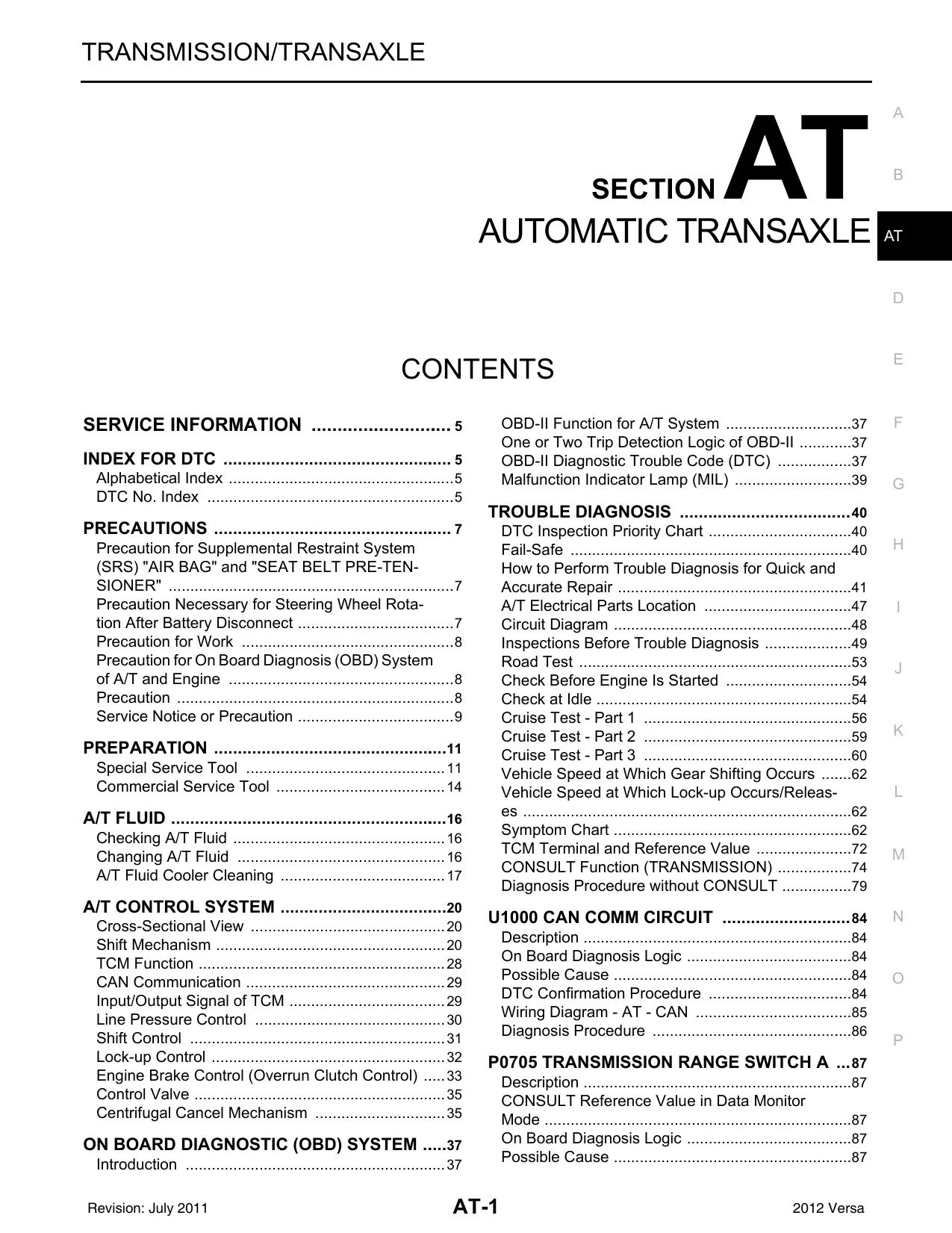
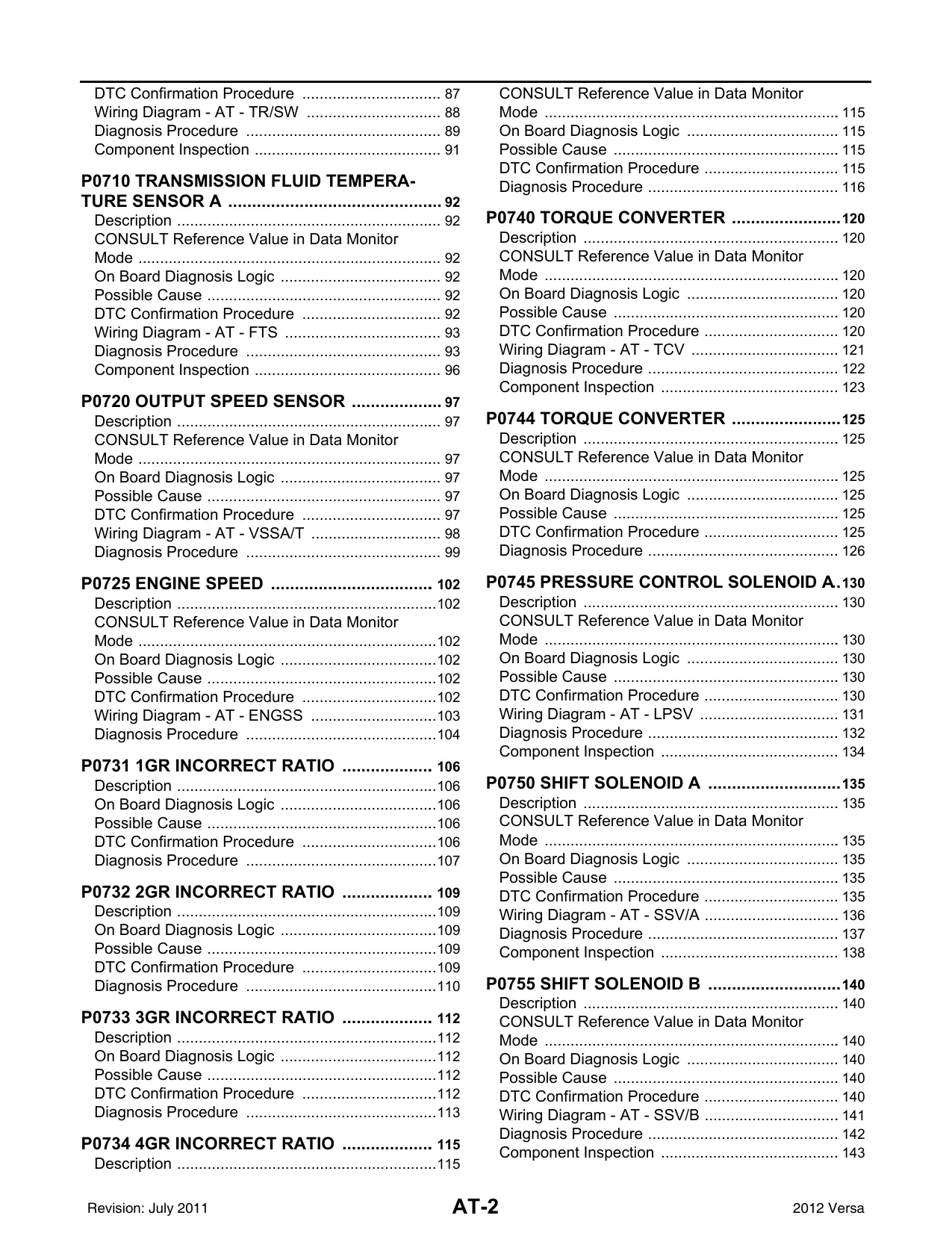
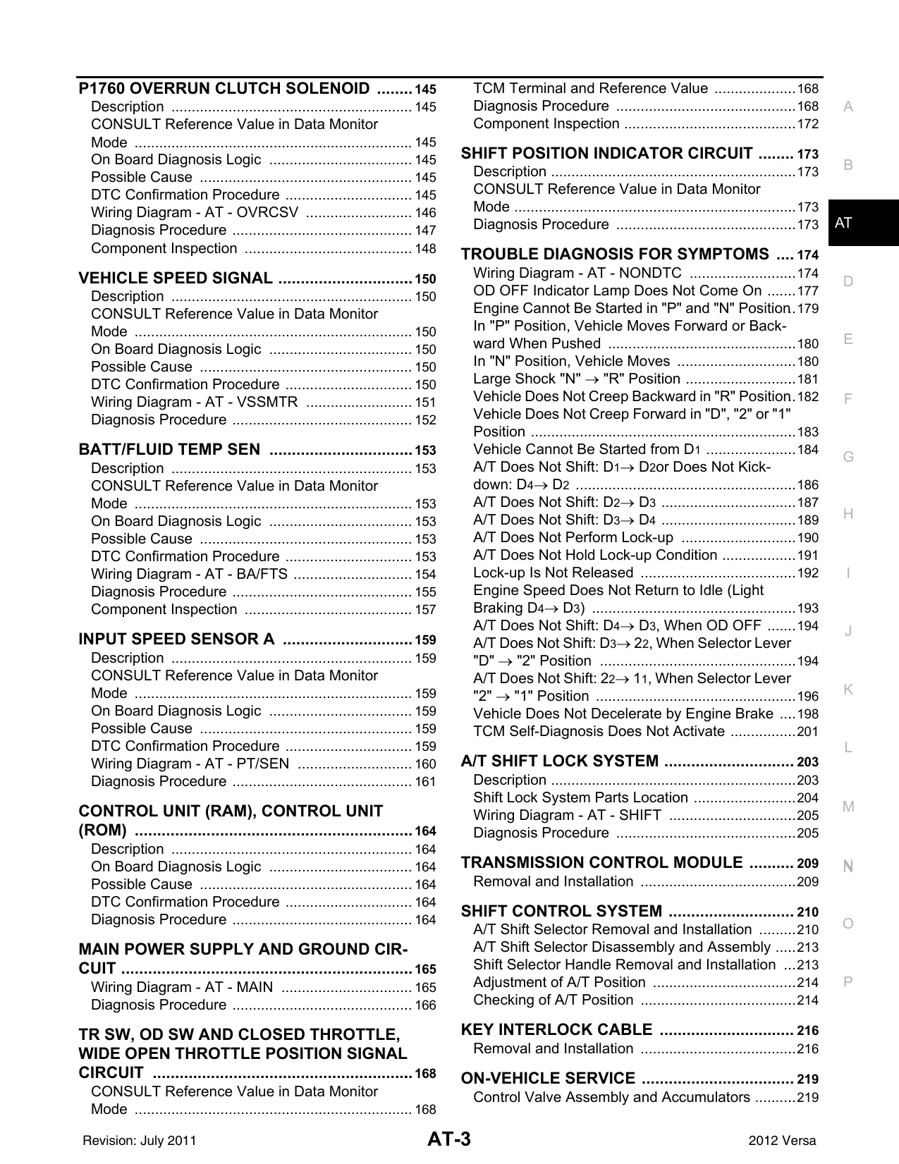
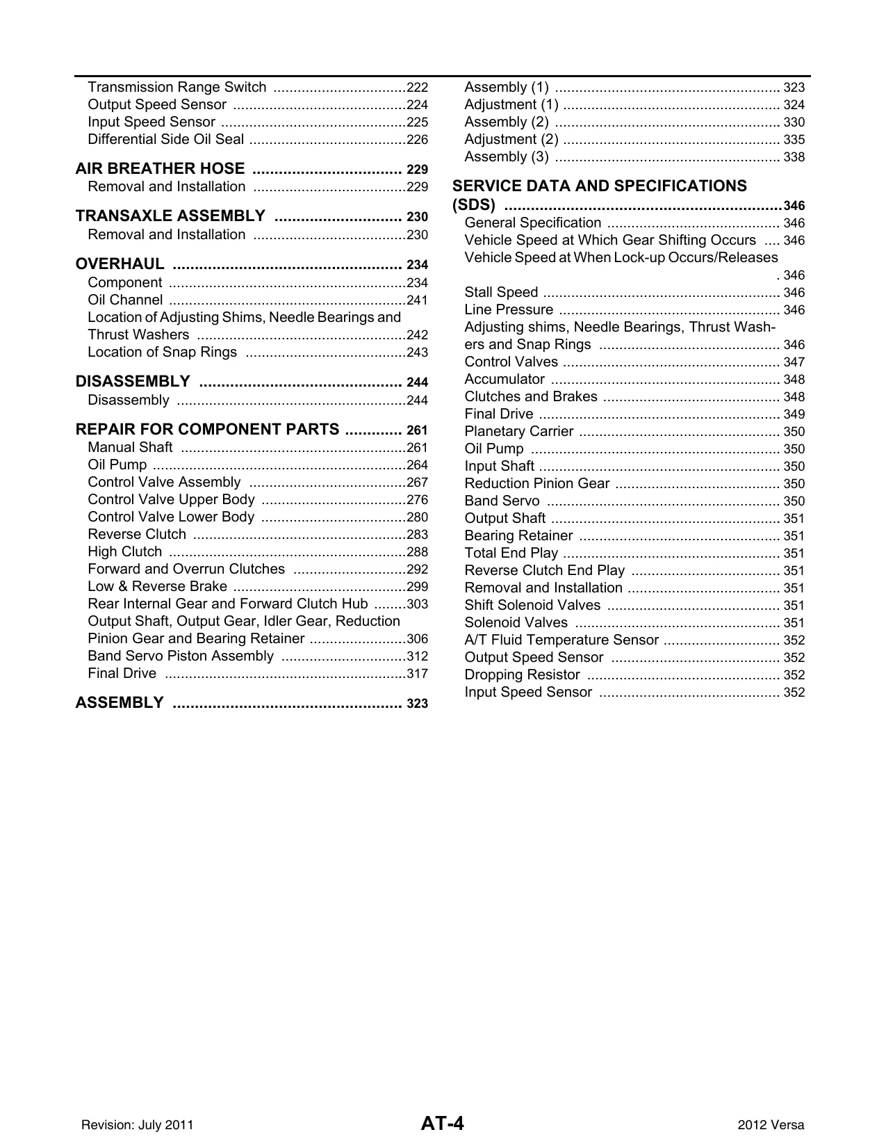
Sample pages from the 2012 Nissan Versa Automatic Transaxle Service Manual manual


Purchase & Download
Models Covered & Key Technical Specifications
Nissan Versa (AT) Automatic Transaxle Manual: Nissan Versa Hatchback manual, covers 2012-2013 Standards-Vault | AT Automatic Transaxle Repository.
- System Components: 23 units form the core of the automatic transaxle system Architecture.
- DTC Index: 46 DTCs provide diagnostic trouble code lookup Function.
- Line Pressure Control: 3 modes manage line pressure to match driving conditions Calibration.
- Shift Solenoid Valves: A and B shift solenoid valves are controlled by the TCM Parameters.
- TCM Input/Output Signals: 29 signals are monitored for control and diagnostics Benchmarks.
- Vehicle Speed Signal: The vehicle speed signal is used for optimal shift timing Baseline.
Professional Workshop Service Manual & Technical Specifications
Nissan Versa (AT) Automatic Transaxle Manual: Nissan Versa Hatchback manual, covers 2012-2013 Standards-Vault
Equipment-Series: AT Automatic Transaxle // Component-Focus: Transmission Control Module Logic // Equipment-Series: 2012-2013 Nissan Versa Service Data
| Component | Parameters | Logic |
|---|---|---|
| Transmission Range Switch | 5 Positions | Input Signals |
| Output Speed Sensor | 2 Sensors | Signal Output |
| Engine Speed Signal | 2 Signals | ECM Input |
| A/T Fluid Temp Sensor | 2 Readings | Sensor Data |
| CAN COMM CIRCUIT | 1 Line | Network Communication |
Outlining the operational framework across the automatic transaxle system, this manual provides detailed procedures for troubleshooting and repair. It covers essential systems and component-level diagnostics. The manual includes a comprehensive technical specifications table for quick reference. Structured maintenance procedures are clearly outlined, ensuring accurate and efficient repair processes. Effectively requiring a methodical approach, this document details the necessary steps for diagnosis and repair of the automatic transaxle system. The manual documents torque specifications for various components to ensure proper joint separation prevention.
FAQ
Customer Reviews
Read what our customers say about this Nissan Car manual and share your own experience.
Add a Review
This policy contains information about your privacy. By posting, you are declaring that you understand this policy:
- Your name, rating, website address, town, country, state and comment will be publicly displayed if entered.
- Aside from the data entered into these form fields, other stored data about your comment will include:
- Your IP address (not displayed)
- The time/date of your submission (displayed)
- Your email address will not be shared. It is collected for only two reasons:
- Administrative purposes, should a need to contact you arise.
- To inform you of new comments, should you subscribe to receive notifications.
- A cookie may be set on your computer. This is used to remember your inputs. It will expire by itself.
This policy is subject to change at any time and without notice.
These terms and conditions contain rules about posting comments. By submitting a comment, you are declaring that you agree with these rules:
- Although the administrator will attempt to moderate comments, it is impossible for every comment to have been moderated at any given time.
- You acknowledge that all comments express the views and opinions of the original author and not those of the administrator.
- You agree not to post any material which is knowingly false, obscene, hateful, threatening, harassing or invasive of a person's privacy.
- The administrator has the right to edit, move or remove any comment for any reason and without notice.
Failure to comply with these rules may result in being banned from submitting further comments.
These terms and conditions are subject to change at any time and without notice.
Reviews (3)